Taco® SKV
17
302-365, Effective: June 5, 2017
© 2017 Taco, Inc.
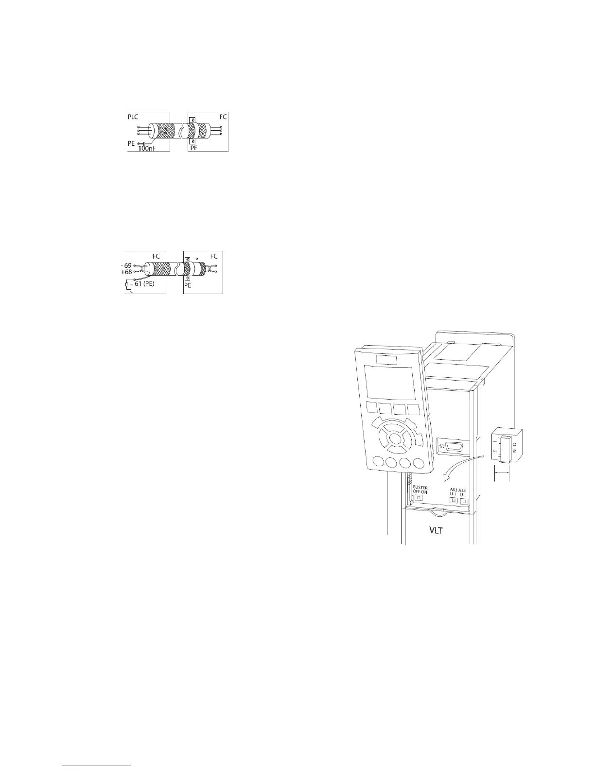
50/60 Hz ground loops
With very long control cables, ground loops may occur.
To eliminate ground loops, connect one end of the shield-
toground with a 100 nF capacitor (keeping leads short).
Avoid EMC noise on serial communication
To eliminate low-frequency noise between adjustable fre-
quency drives, connect one end of the shield to terminal
61. This terminal is connected to ground via an internal
RC link. Use twisted-pair cables to reduce interference
between conductors.
Control Terminal Functions
Adjustable frequency drive functions are commanded by
receiving control input signals.
• Each terminal must be programmed for the function it
will be supporting in the parameters associated with
that terminal.
• It is important to confirm that the control terminal is
programmed for the correct function. See “9 User
Interface” on page 28for details on accessing param-
eters..
• The default terminal programming is intended to initi-
ate adjustable frequency drive functioning in a typical
operational mode.
Jumper Terminals 12 and 27
A jumper wire may be required between terminal 12 (or
13) and terminal 27 for the adjustable frequency drive to
operate when using factory default programming values.
• Digital input terminal 27 is designed to receive an
24VDC external interlock command. In many appli-
cations, the user wires an external interlock device to
terminal 27.
• When no interlock device is used, wire a jumper
between control terminal 12 (recommended) or 13 to
terminal 27. This provides an internal 24 V signal on
terminal 27.
• No signal present prevents the unit from operating.
• When the status line at the bottom of the LCP reads
“AUTO REMOTE COASTING” or “Alarm 60 External
Interlock” is displayed, this indicates that the unit is
ready to operate but is missing an input signal on ter-
minal 27.
• When factory installed optional equipment is wired to
terminal 27, do not remove that wiring.
Terminal 53 and 54 Switches
• Analog input terminals 53 and 54 can select either
voltage (0 to 10V) or current (0/4–20mA) input sig-
nals
• Remove power to the adjustable frequency drive
before changing switch positions.
• Set switches A53 and A54 to select the signal type. U
selects voltage, I selects current.
• The switches are accessible when the LCP has been
removed (see Figure 8-17). Note that some option
cards available for the unit may cover these switches
and must be removed to change switch settings.
Always remove power to the unit before removing
option cards.
• Terminal 53 default is for a speed reference signal in
open-loop set in 16-61 Terminal 53 Switch Setting
• Terminal 54 default is for a feedback signal in closed-
loop set in 16-63 Terminal 54 Switch Setting
Figure 8-17: Location of Terminals 53 and 54
Switches