Taco® SKV
21
302-365, Effective: June 5, 2017
© 2017 Taco, Inc.
8.4.2 Relay Outputs
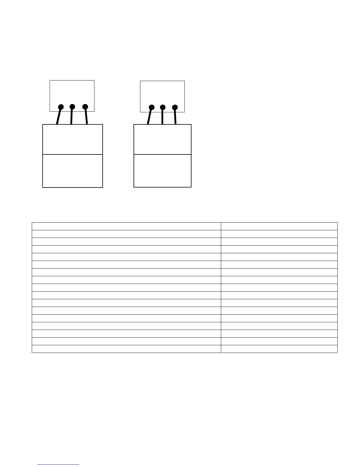
As shown above, each unit has two form C programmable relay outputs. The relay terminals can be found on the con-
troller in various locations according to the frame size.
Figure 8-19: Wiring the Relay Terminals
01
COM
Relay 1
02
NO
03
NC
04
COM
Relay 2
05
NO
06
NC
COM
NO
NC
Unit Receiving
Output from
Relay 1
[5-40.0]
[160] No Alarm*
No Alarm: Comm=NO
Alarm: Comm = NC
COM
NO
NC
Unit Receiving
Output from
Relay 2
[5-40.1]
[5] Running*
Running: Comm=NO
Off: Comm = NC
* Factory Default Settings
Table 3: Relay Terminal Specifications
Programmable relay outputs 2
Relay 01 Terminal number 1–3 (break), 1–2 (make)
Maximum terminal load (AC-1) on 1–3 (NC), 1–2 (NO) (Resistive load) 240 V AC, 2A
Maximum terminal load (AC-15) (Inductive load @ cos 0.4) 240 V AC, 0.2A
Maximum terminal load (DC-1) on 1–2 (NO), 1–3 (NC) (Resistive load) 60 V DC, 1A
Maximum terminal load (DC-13) (Inductive load) 24 V DC, 0.1A
Relay 02 Terminal number 4–6 (break), 4–5 (make)
Maximum terminal load (AC-2) on 4–5 (NO) (resistive load) 400 V AC, 2A
Maximum terminal load (AC-15) (Inductive load @ cos 0.4) 240 V AC, 0.2A
Maximum terminal load (DC-1) on 4–5 (NO) (Resistive load) 80 V DC, 2A
Maximum terminal load (DC-13) on 4–5 (NO) (Inductive load) 24 V DC, 0.1A
Maximum terminal load (AC-1) on 4–6 (NC) (Resistive load) 240 V AC, 2A
Maximum terminal load (AC-15) on 4–6 (NC) (Inductive load @ cos 0.4) 240 V AC, 0.2A
Maximum terminal load (DC-1) on 4–6 (NC) (Resistive load) 50 V DC, 2A
Maximum terminal load (DC-13) on 4–6 (NC) (Inductive load) 24 V DC, 0.1A
Minimum terminal load on 1–3 (NC), 1–2 (NO), 4–6 (NC), 4–5 (NO) 24 V DC 10mA, 24 V AC 20mA
Environment according to EN 60664–1 overvoltage category III/pollution degree 2