Taco® SKV
25
302-365, Effective: June 5, 2017
© 2017 Taco, Inc.
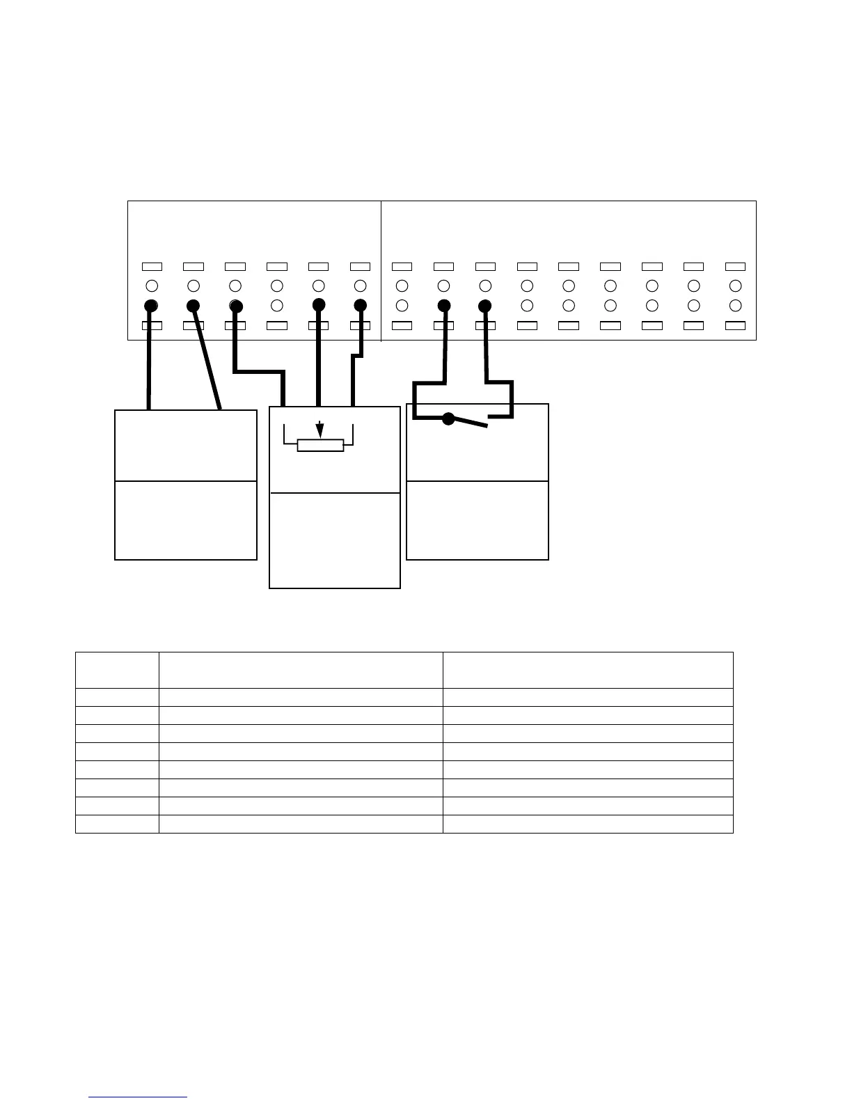
8.4.4 Speed control with external potentiometer
This configuration allows an external potentiometer to control the speed of the motor.To use this set-up, the analog
input must be configured as a voltage input.
The following wiring scheme is used with Set-up 2 as shown in “10.1 SelfSensing Description” on page 34.
Figure 8-23: Terminal Wiring for Potentiometer used as External Speed Reference
39
COM
42
AOUT
50
+10V
53
A IN
55
COM
54
A IN
12
+24V
13
+24V
18
D IN
19
D IN
27
D IN
29
D IN
32
D IN
33
D IN
20
COM
I/O Analog I/O Digital
COM
AI
Unit Receiving
Analog Output
[6-50]
[137] Speed*
4-20 mA
* factory default
Starting/Stopping
Controller
[5-10]
[8] Start*
Start: Closed
* factory default
+10V
COM
[1-00] [0] Open Loop
[3-15] [1] AI54
(See Table)
Set A54=U
AI53
Speed Control
Potentiometer
Group 6-
Group 20-
(Optional)
To set up the controller for speed control with an external potentiometer, set the following parameters:
* Set switch A54 = U
Parameter
number
Description Set to
1-00 Configuration Mode Open Loop
3-15 Reference 1 Source Analog Input 54
6-20 Terminal 54 Low Voltage* 0 V
6-21 Terminal 54 High Voltage* 10 V
6-24 Terminal 54 Low Ref./Feedb. Value 0
6-25 Terminal 54 High Ref./Feedb. Value Maximum motor speed. For example, 2950 Hz.
6-27 Terminal 54 Live Zero Disabled.
20-00 Feedback 1 Source No Function