Taco® SKV
27
302-365, Effective: June 5, 2017
© 2017 Taco, Inc.
* To use AI 53, configure parameters 6-14, 6-15, 6-17 and set 20-00 to Analog Input 53
8.4.6 Control From External PLC/BMS Using Communications Port
The controller can be controlled from a BMS or PLC through the communications port. In this configuration, the BMS or
PLC overrides the setpoint to control the drive. Control cables must be braided screened/shielded and the screen must
be connected to the metal cabinet of the controller using two cable clamps (one at each end). The bus connections
must be terminated by turning the BUS TER switch to the on position. This switch can be found under the LCP, when
the LCP is detached.
This wiring scheme is used with Set-up 2, as shown in “10.1 SelfSensing Description” on page 34.
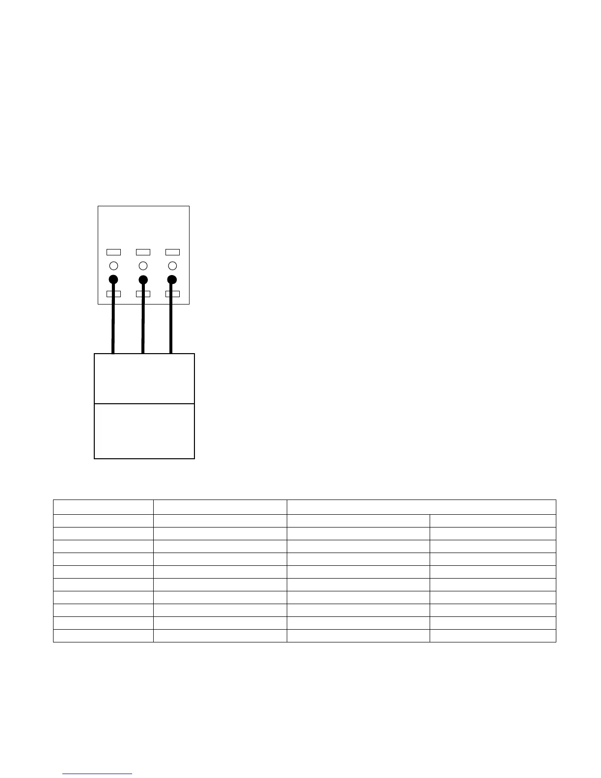
Figure 8-25: Terminal Connections for External Control via Communications Port
69
-
68
+
61
SHLD
Comm Port
SHLD
-
RS485
Controller
[8-**] Config params
+
Table 7: Parameter settings for Modbus RTU and BACnet protocols
The parameters above show a typical scenario used for Modbus RTU or BACnet protocols. The parameters must be
set as appropriate for the devices on the network. 8-32 Baud Rate and 8-33 Parity/Stop Bit should be set to match the
other devices on the network. For specific communication set-up information for Modbus RTU, refer to the document
number MG92B102. For specific communication set-up information for BACnet, see documents MG14C102 and
MG11D202. These documents can be downloaded from www.danfoss.com.
Parameter Number Parameter Description Protocol
Modbus RTU BACnet
8-02 Control Source FC Port FC Port
8-30 Protocol Modbus RTU BACnet
8-31 Address 1 1
8-32 Baud Rate 19200 9600
8-33 Parity/Stop bit Even Parity, 1 Stop bit No Parity, 1 Stop bit
8-34 Estimated cycle time 0 ms 0 ms
8-35 Minimum Response Delay 10 ms 10 ms
8-36 Maximum Response Delay 5000 ms 5000 ms
8-37 Maximum Inter-Char Delay 0.86 ms 25 ms