EasyManua.ls Logo

Taie FY800 - FY400 Terminal Arrangement

Default Icon
89 pages
Print Icon
To Next Page IconTo Next Page
To Previous Page IconTo Previous Page
Loading...
17 FY operation manual
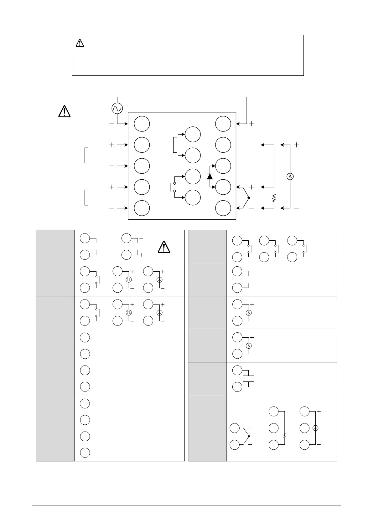
8. Terminal Arrangement
Caution
When implementing wiring for the controller power supply, please make sure that the power supply is
turned off to avoid electric shock!
Do not touch the live parts, such as the terminals, while the power is on. Otherwise death or serious
injury may be resulted from short circuit of the contact electrode.
8.1 FY400 Terminal Arrangement
Power supply
AC 85~265V
DC 24V
AL2
A
B
B
INPUT
TC/mV
COMM
T/R (A+)
T/R (B-)
RTD mA/V
1
2
3
4
5
8
11
12
13
14
6
7
9
10
Relay
SSR
mA/V
OUT2
(AL1)
Relay
SSR
mA/V
OUT1
4
5
mA / VSSR
4
5
4
5
Relay
1
6
DC 24V
1
6
AC 85~265V
L
N
2
3
mA / VSSR
2
3
2
3
Relay
11
12
mA / V
11
12
mA / V
TC / mV
9
10
7
9
10
A
B
B
RTD
7
9
10
mA / V
G1
11
12
13
14
K1
K2
G2
13
14
AL2
2
3
11
12
AL1
or
2
3
4
5
CLOSE
COM
OPEN
Power
Output-1
Output-2
1ϕ Zero cross
Motor
valve
Transmission
Remote SV
Input
Alarm-1
Alarm-2
Communication
11
12
CT
CT
RS-485
11
12
T/R (A+)
T/R (B-)

Table of Contents

Other manuals for Taie FY800

Related product manuals