FY operation manual 68
14. Modification of Output Module
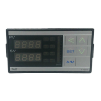
14.1 Relay Control (1a)
Parameter set as “CYT1 =10”
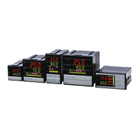
14.2 Relay Control (1c)
Parameter set as “CYT1 =10”
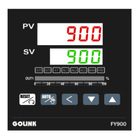
14.3 SSR Control
Volt module
VOLT
_Pulse
-K1712
Made In Taiwan
Pb
Parameter set as “CYT1 =1”
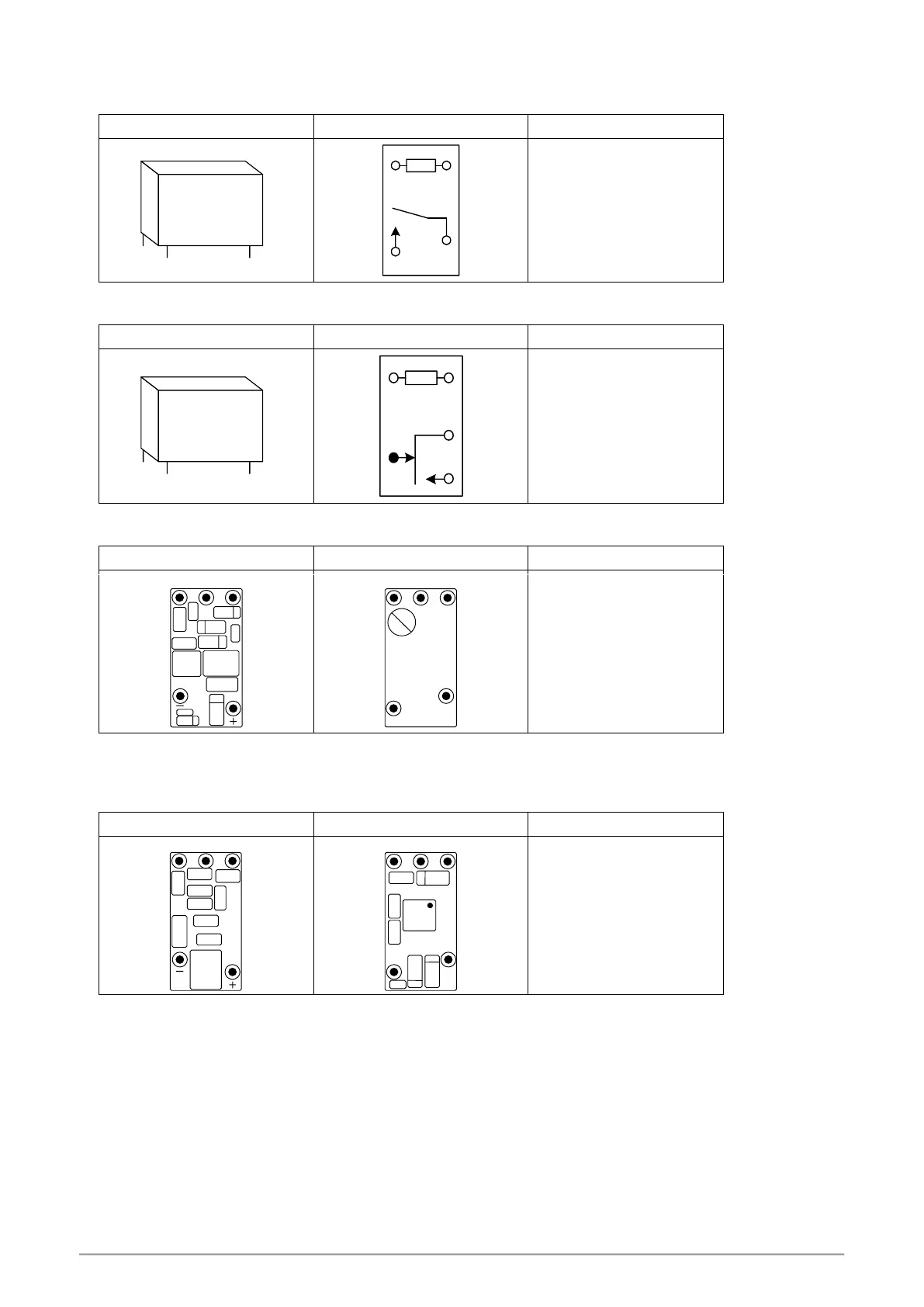
14.4 Linear Control
※ : When modifying mA current module, output signal needs to be calibrated, and for detailed calibration procedure,
please refer to Chap. 14.5 Output Calibration Procedure Diagram.
Parameter set as “CYT1 =0”
 Loading...