C2.8 T854 Circuit Operation M8SL2-00-002-812
© Copyright Tait Electronics Limited August 2004. All rights reserved.
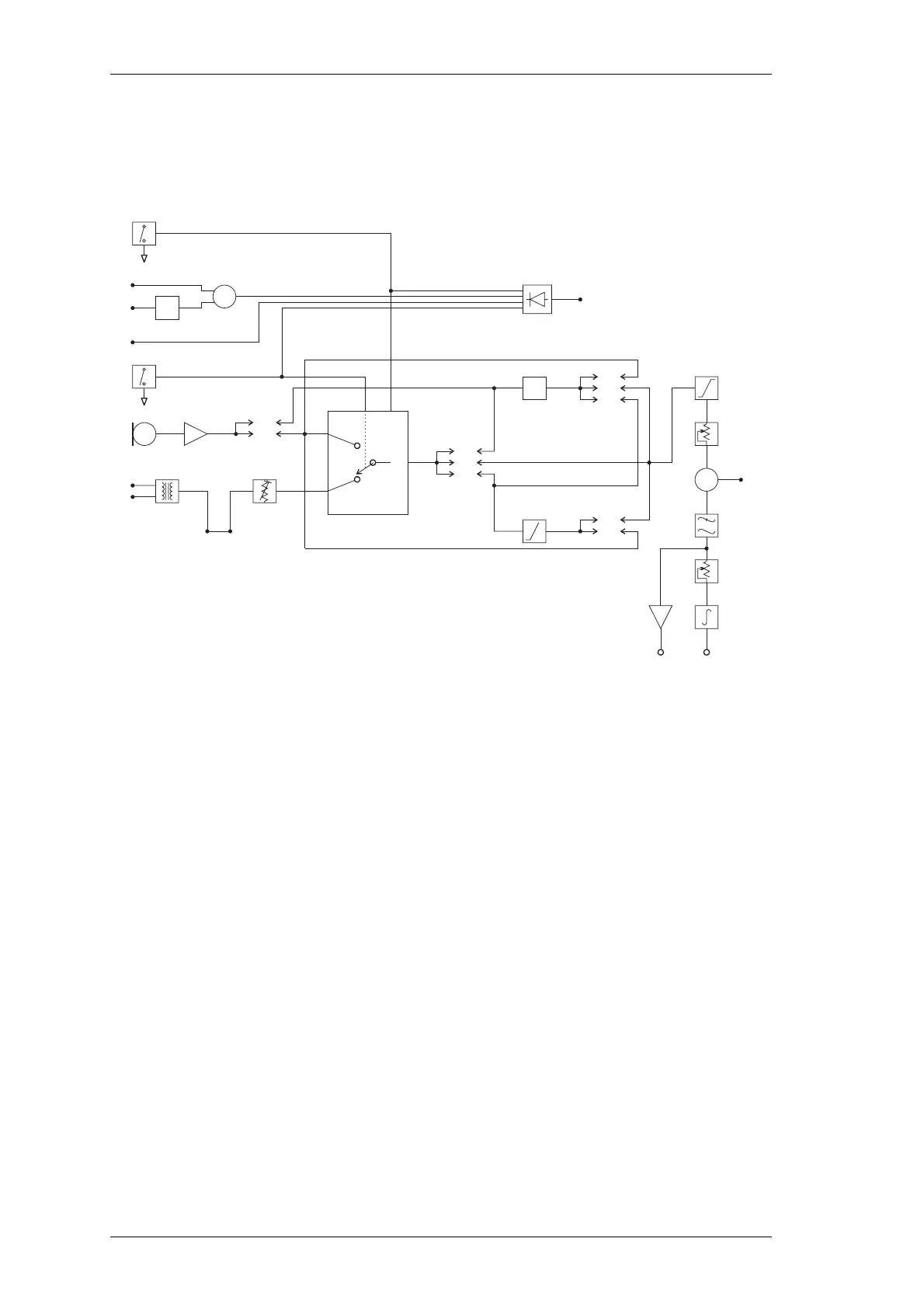
2.5 Audio Processor
Refer to the audio processor circuit diagram (Sheet 2 – T854 Audio Processor) in Section
6.2.
Figure 2.5 T854 Audio Processor Block Diagram
2.5.1 General
The audio processor comprises several link selectable circuit blocks which may be con-
figured in a variety of combinations to suit individual requirements. The pre-emphasis
network and compressor may be linked individually or cascaded between either or both
audio inputs and the limiter.
Refer to Section 3.5.1 for linking details.
2.5.2 Audio Inputs
Two audio inputs are available: one from a 600Ω balanced (or unbalanced) line, and the
other from a local microphone. The microphone signal is passed first to a pre-amplifier
(Q210) and ultimately to a multiplexer (IC240), but in between may pass through the
compressor (depending on the linking details). The line transformer is also connected to
the multiplexer and is disabled by the microphone PTT switch.
A third input for external CTCSS tones is also provided.
Pre-
emphasis
34
6
B
C
5
14
2
910
8
13
1
11
3
5
910
6
N
H
M
I
E
L
J
D
12
4
7
mic.
line
Multiplexer
Inputs
Output
Output
Inhibit
Audio 1 Audio 2
Compressor
Link
Link
Link
Tx Enable
Σ
Carrier
Opto-Key
Tx Key
PTT
Microphone
Input
Line Input
Microphone
Pre-amp.
Opto-coupler
Link
PL201
PL202
PL201
PL202
Limiter
Set Deviation
CTCSS
Low Pass
Filter
Ref. Mod. Adjust
Integrator
Digital Pot. (EPOT)
Digital Pot. (EPOT)
Buffer
Output
To VCO
Ref.
Mod.
Constant Current Sink
+
_

 Loading...


