M8SL2-00-002-812 Functional Testing F4.1
© Copyright Tait Electronics Limited August 2004. All rights reserved.
4 Functional Testing
The following test procedures will confirm that the T800-23-0011 has been set up and
adjusted correctly and is fully operational. Refer to Figure 4.1 for test equipment details.
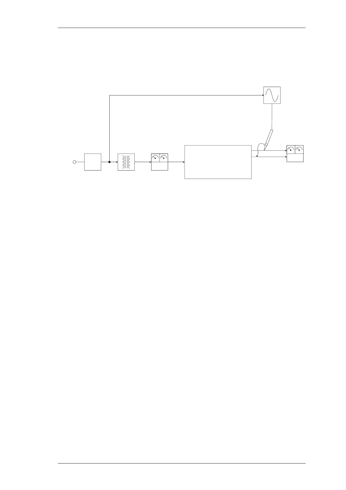
Figure 4.1 Test equipment setup
4.1 Basic Operation
To confirm the basic operation of the power supply, proceed as follows.
• Ensure that the main supply to the T800-23-0011 is switched off. Set up the
test equipment as shown in Figure 4.1.
• Set the output DC load to maximum resistance/minimum current.
• Connect the T800-23-0011 to the mains supply and switch it on.
• Vary the DC load and check that the output voltage and current are within
the specifications (refer to Section 1.2.4).
4.2 Output Current Overload
To confirm the operation of the current overload protection circuitry, proceed as follows.
• Ensure that the main supply to the T800-23-0011 is switched off. Set up the
test equipment as shown in Figure 4.1.
• Set the output DC load to draw approximately 11A.
• Switch on the mains supply and slowly decrease the load resistance, thereby
increasing the current until voltage foldback occurs. The current should not
rise above the Current Overload Limit (refer to Section 1.2.4), but voltage
should drop away.
Earth
Leakage
Circuit
Breaker
VA__
*
Mains
Supply
Isolating
Transformer
1kVA
Variac
0 to 260V
1kVA
AC
* True RMS Reading
T800-23-0011 PSU
+
-
AC
Input
Output
VA__
DC Load
0 to 30A
DC
Oscilloscope

 Loading...


