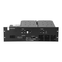
M8SL2-00-002-812 T854 Initial Tuning and Adjustment C3.15
© Copyright Tait Electronics Limited August 2004. All rights reserved.
The following table indicates the SL2 backplane configuration required.
3.10.1 T1500-52-0000 Tx Alarm/Multi-channel Kit
When fitted, the T1500-52-0000 Tx alarm PCB monitors the transmitter output power
and generates a low forward and/or high reverse power alarm signal as appropriate.
Alarm outputs are compatible with the T1511-20-0000 CCM module. On-board LED
indication of alarms is also provided for trouble shooting and setup purposes.
Parts Supplied
The T1500-52-0000 should contain:
• T1500-52-0000 Alarm PCB and mounting screws.
• D-range and PCB interface.
3.10.1.1 Installation
To install this kit you will require the following tools:
• T1500-52-0000 Tx alarm/Multi-channel alarm kit
• Philips screwdriver
• Soldering iron
• Small sidecutters
Alarm board
SL2 Backplane
Notes
Link 9 Link 10
T1500-52-0000
(PCB 220-01426-04)
2 – 32 – 3
See Section 3.10.1 T1500-52-
0000 Tx Alarm/Multi-channel
Kit
T800-10-0520 (plug-in alarm
board)
2 – 32 – 3
See Section 3.10.2 T800-10-0520
Tx-Alarm/Channel-Select Kit
No internal alarm board fitted
but FWD and REV power
sense voltages output directly
on T854 Aux D-range. Could
be used for an externally fitted
RF power indicator/alarm.
1 – 21 – 2
Cannot be used to trigger
T803-02 RF power alarms.
On the T854 for S/N 13098764
or earlier:
– remove R840 and R841
– fit R308 and R310 (both 10kΩ)

 Loading...