M8SL2-00-002-812 T855 Fault Finding B5.17
© Copyright Tait Electronics Limited August 2004. All rights reserved.
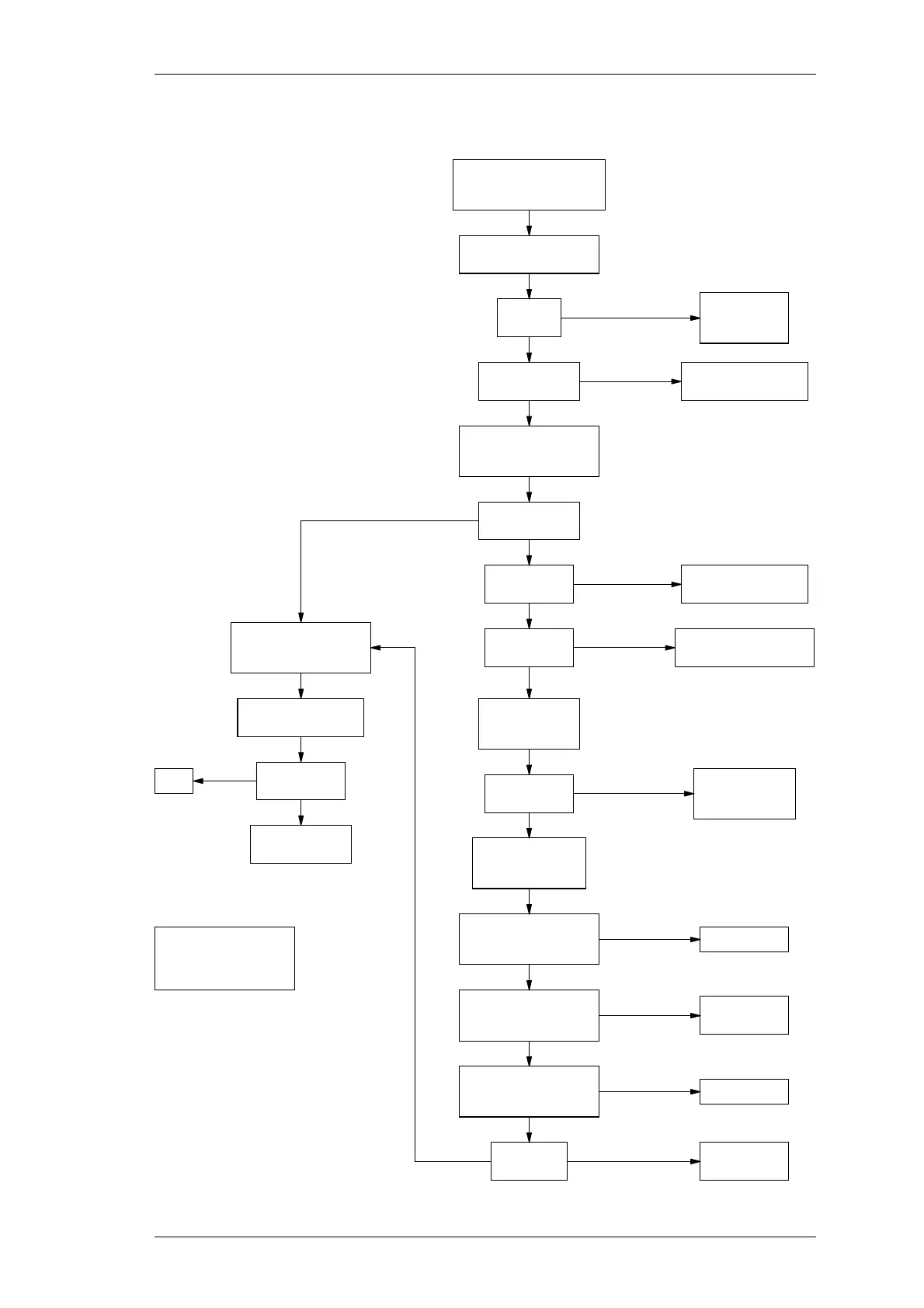
5.7.5 Carrier Mute
Approx. 5V on
RSSI pad 238?
Approx. 5V on
IC280 pin 1?
Check/replace IC280
& adjoining components.
Check Q230, Q245 &
Q290 for operation.
Adjust RV235 &
observe voltage
on IC280 pin 6.
Switch SW201
(monitor mute) to ensure
mute is enabled.
Y
N
N
N
Y
Y
Does "Gate" LED
toggle on/off?
Refer to
receiver fault
finding chart.
N
Y
Y
Voltage varies
0-6V?
Check 9V rail &
resistors R275,
R277 & RV235.
Y
N
Set RF signal level
to -95dBm. Rotate
RV235 c/w & cc/w.
Monitor voltage on
IC280 pin 7. Switching
0-8V as RV235 rotated?
Replace IC280.
N
Y
Monitor voltage on
IC270 pin 7. Switching
0-8V as RV235 rotated?
Check/replace
IC270 & D240.
N
Y
Monitor voltage on
pad 234. Switching
0-8V as RV235 rotated?
Replace Q250.
N
Y
Does "Gate"
LED toggle?
Check/replace
Q255 & D250.
YN
Mutable audio
on outputs?
OK
N
Y
Refer to audio
fault finding chart.
Note:
c/w = clockwise
cc/w = counterclockwise
or anticlockwise
Rotate RV235
(carrier mute) c/w & cc/w
& view "Gate" LED.
Apply on channel signal
@ -110dBm* to receiver.
Audio on
TP314?
*Modulated by 1kHz signal with
±3kHz (±2.4kHz) [±1.5kHz] deviation.
Approx. 2V at
D-Range 1 pin 5?
N
Ensure PL250 is set
for carrier mute operation,
and the RSSI PCB is fitted.
Check for short circuits
and/or replace IC310.
Check Q340 and
adjoining components.
 Loading...


