M8SL2-00-002-812 Installation Guidelines F3.1
© Copyright Tait Electronics Limited August 2004. All rights reserved.
3 Installation Guidelines
The following section gives a brief description of the basic rack mounting and wiring
procedures.
3.1 General
The T800-23-0011 is supplied mounted to the SL2 front panel by four M3x10 button hex
screws.
A small cable extending out of the front of the T800-23-0011 plugs onto to the SL2 front
panel. This cable forms part of the programming and speaker connection between the
SL2 front panel and the backplane. The external cable connection between the
T800-23-0011 and the SL2 backplane provides the DC power supply to the basestation
and also incorporates 3 wires completing the programming and speaker connection.
Warning: FUSE
The cable connecting the T800-23-0011 DC power output to the backplane
also includes a fuse. This fuse is critical to the IEC 60950 safety compliance
of the T800 SL2 Base Station and must be replaced with the same component
or compliance will be voided.
The Fuse is a Bussmann TDC10 Series fast blow fuse rated at 12A (60V
AC
)
For the AC mains input connection of the T800-23-0011 use only an IEC type detachable
power supply cord (with a moulded IEC connector). Ensure that it has a current rating
of at least 5A.
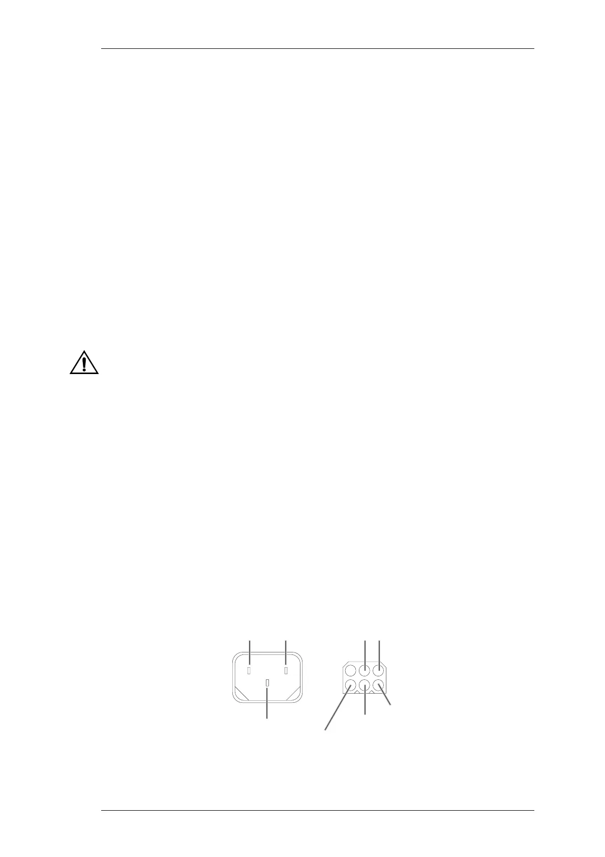
3.2 Connector Pinouts
The pinouts for the AC mains input connector and the DC output connector on the rear
of the T800-23-0011 are shown in Figure 3.1 below.
Figure 3.1 Connector Pinouts on the T800-23-0011 rear panel.
Ground+13.8VLive
Earth
Neutral
IEC Plug (Mains Input) Molex Socket (DC Output)
Ground
Programming port
(from front panel)
Speaker
(to front panel)

 Loading...


