C3.8 T854 Initial Tuning and Adjustment M8SL2-00-002-812
© Copyright Tait Electronics Limited August 2004. All rights reserved.
3.5 Audio Processor Links
3.5.1 Link Details
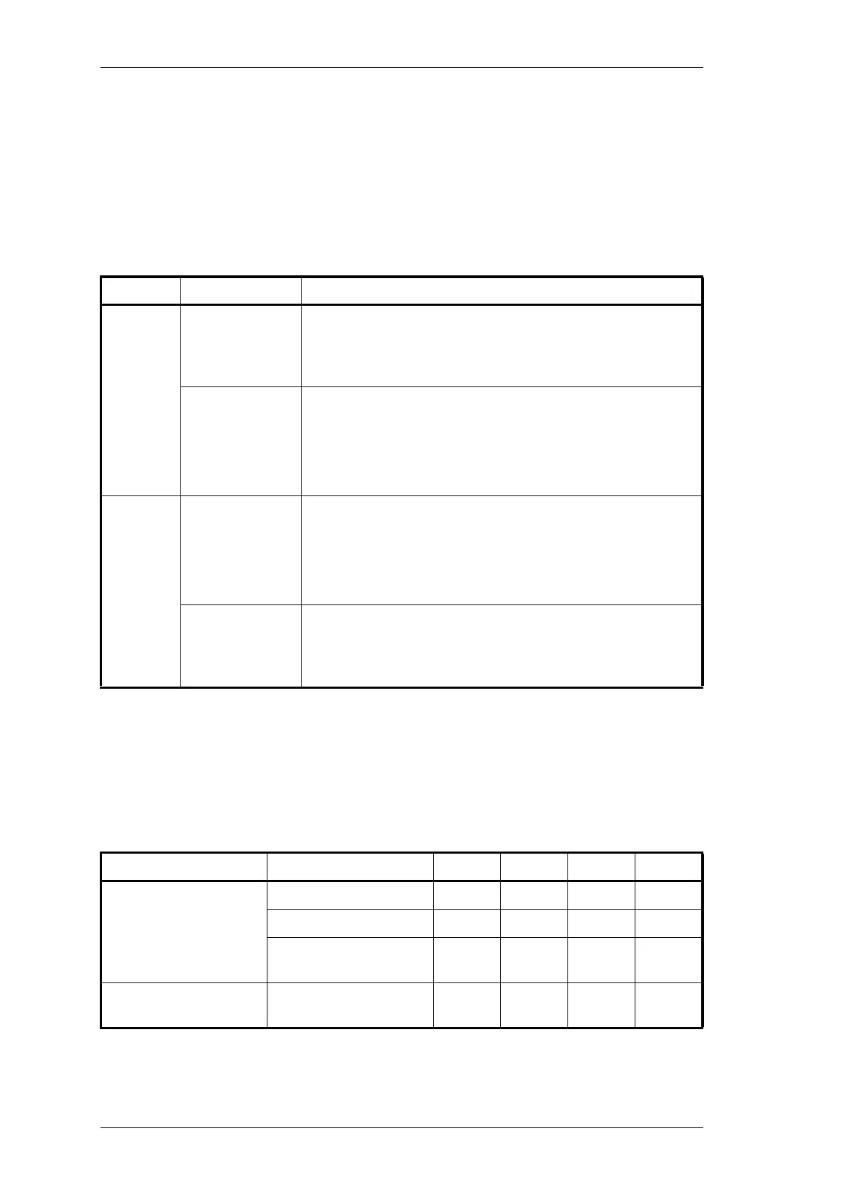
Use the following table to set up the audio processor to the configuration you require.
You should set the audio processor links before carrying out any of the tuning and
adjustment procedures.
3.5.2 Typical Options
Plug Link
a
a The letters in this column refer to the letters printed on the PCB beside each pair of pins.
Note that the link names and pin numbers are different to earlier products. The lettering A
to N is however the same.
Function
PL201
1–2
3–4
b
5–6
b Factory Setting
A
B
C
not connected
microphone pre-amp output to compressor input
microphone pre-amp output to multiplexer input
7–8
9–10
b
11 –12
13–14
D
E
F
G
pre-emphasis output to multiplexer input
pre-emphasis output to limiter input
not connected
not connected
PL202
1–2
b
3–4
5–6
7–8
H
I
J
K
compressor output to multiplexer input
compressor output to limiter input
compressor output to pre-emphasis input
not connected
9–10
b
11 –12
13–14
L
M
N
multiplexer output to pre-emphasis input
multiplexer output to limiter input
multiplexer output to compressor input
microphone pre-amp line input PL201
a
a The letters in this table refer to the letters printed on the PCB beside each pair of pins.
PL201 PL202 PL202
compressed and
pre-emphasised
pre-emphasised B
b
b Factory Setting
E
b
H
b
L
b
unprocessed B D J M
compressed and
pre-emphasised
CE JN
compressed and
flat response
flat response
BFHM
 Loading...


