F6.2 Service Information M8SL2-00-002-812
© Copyright Tait Electronics Limited August 2004. All rights reserved.
6.2 Mechanical
This section provides information necessary for replacement of various parts and mod-
ules of the T800-23-0011 power supply.
Warning: Safety approval will become void if T800-23-0011 components are
replaced with non-equivalent rated or non-certified/approved compo-
nents. Contact Tait Electronics Technical Support before replacing compo-
nents of the T800-23-0011.
The power supply module is not a user serviceable item. This module
contains components that operate at voltages that may be lethal. Do not
open this module.
Caution: Disconnect the mains IEC connector and wait for 5 minutes for the internal
voltages to drain away before dismantling the T800-23-0011.
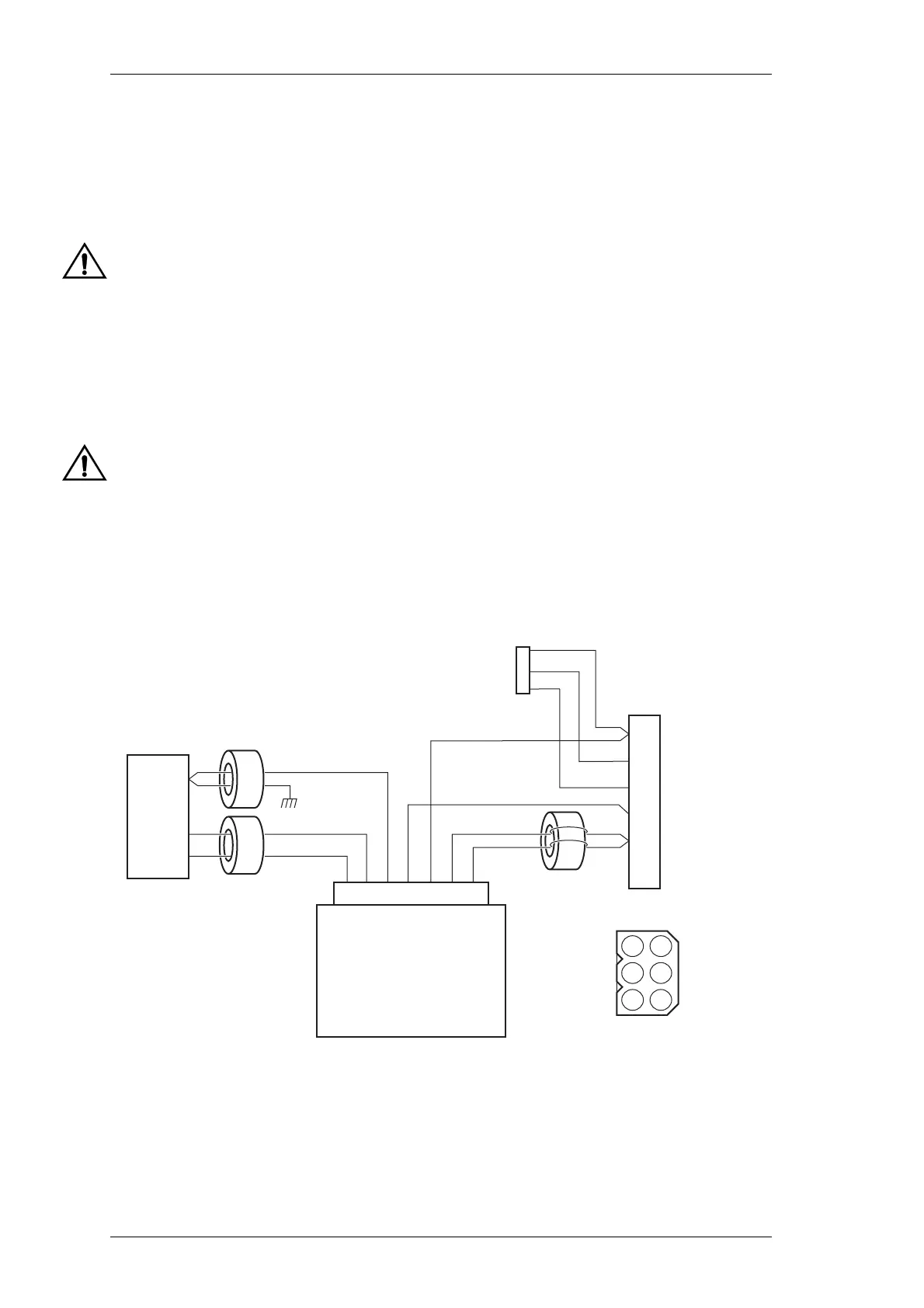
6.2.1 Wiring Diagram
Refer to the diagram below for connection information between the T800-23-0011’s con-
nectors and powers supply module.
Figure 6.1 T800-23-0011 Wiring Diagram
Molex
Connector
1
2
3
4
5
6
7
+13.8V
Black
Live
Neutral
Ferrite Sleeve
Ferrite Beads
PSU Module
EC Mains
onnector
Chassis
Ground
Ground
Green&Yellow
Blue
Brown
Red
Black
Red
1
2
3
4
5
6
3
2
1
6
5
4
Yellow
Red
Brown
Front panel programming port
and speaker connection
Gnd
Gnd
External view

 Loading...


