C2.10 T854 Circuit Operation M8SL2-00-002-812
© Copyright Tait Electronics Limited August 2004. All rights reserved.
2.6 Power Supply and Regulator Circuits
Refer to the regulators circuit diagram (Sheet 6 – T854 Regulators) in Section 6.2.
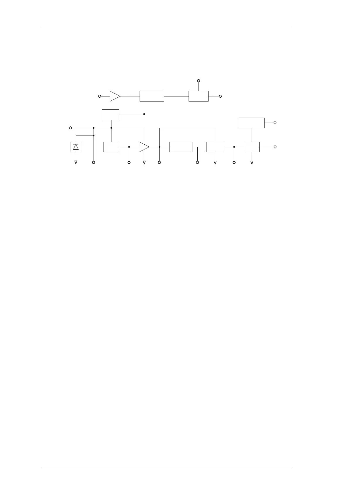
Figure 2.6 T854 Power Supply and Regulators Block Diagram
The T854 is designed to operate from a 10.8 to 16V
DC
supply (13.8V nominal). A 5.3V
regulator (IC630) runs directly from the 13.8V rail, driving much of the synthesiser cir-
cuitry. It is also used as the reference for a DC amplifier (IC640, Q630, Q620) which
provides a medium current capability 9V supply. The T854 has a regulator (IC370)
which produces 9V for use in the exciter and audio circuits.
A switching power supply (Q660, Q670) runs from the 9V supply and provides a low
current capability +20V supply. This is used to drive the synthesiser loop filter (IC750),
giving a VCO control voltage range of up to 20V.
Ultimate control of the transmitter is via the Tx-Reg. supply, switched from 9V by Q610.
This is enabled via the Tx-Enable signal from the audio processor, and microprocessor.
A crowbar diode is fitted for protection against connection to a power supply of incor-
rect polarity. It also provides transient overvoltage protection.
Note: A fuse must be fitted in the power supply line for the diode to provide effec-
tive protection.
Crowbar
Diode
LVI
5V
Reg
DC
Amp
Switching
PS
5V Dig
Reg
Power
Switch
13.8V
Nom.
5V 5V Dig9V 20V
13.8V Nom.
From Rear
D-Range
Tx Enable
Buffer
Tx Reg.
+9V
µP
Watchdog
Timer
Micro-
controller
µP
Reset
9v Reg
IC 370
9v Ex

 Loading...


