TB8100 Installation and Operation Manual Description 13
© Tait Electronics Limited June 2005
can also be removed from the subrack by undoing a single screw. Refer to
“Replacing Modules” on page 87 for more details.
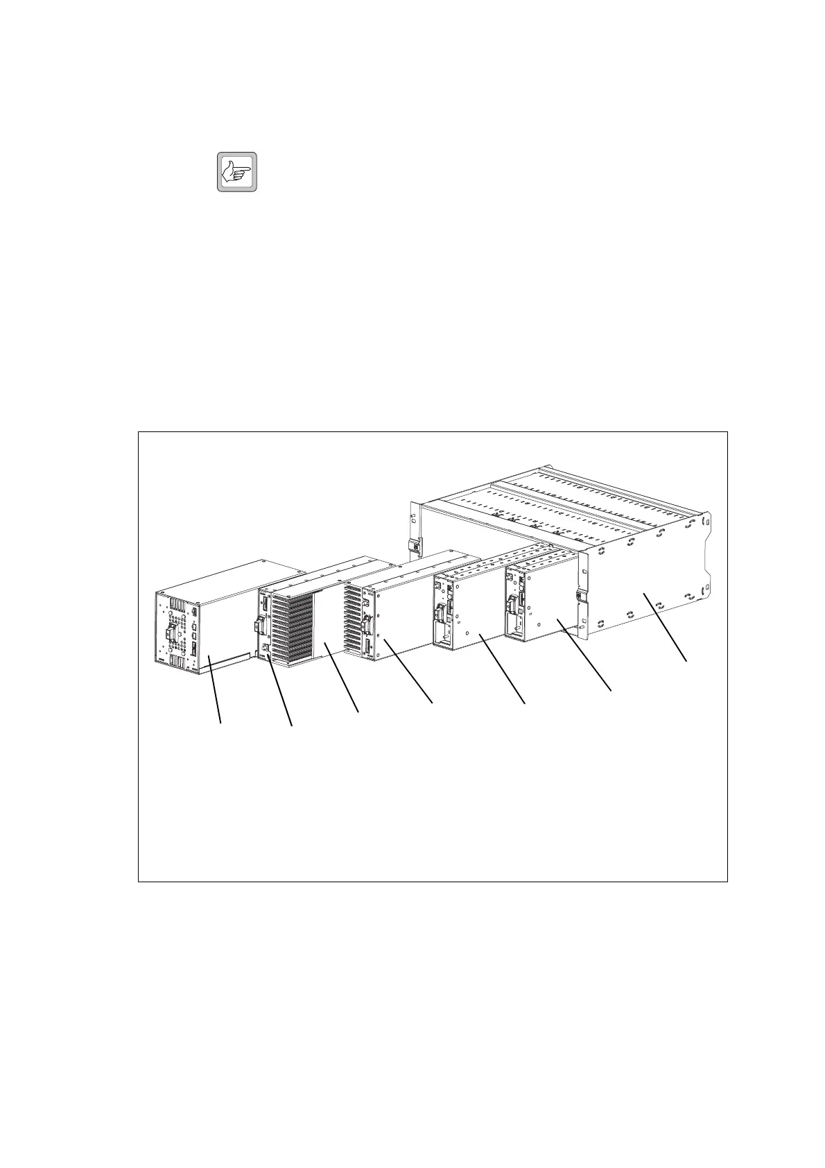
Note Figure 1.1 shows the cooling fans and their ducts detached from
the front panel only for the clarity of the illustration. The cooling
fans and ducts are normally screwed to the rear of the front panel.
Figure 1.1 also shows the configuration for a typical single 5W or 50W base
station. The PMU occupies the slot at the left end of the subrack, with the
PA directly beside it. The single reciter normally occupies the second slot
from the right of the subrack.
The single PA is mounted vertically with the heatsink facing the centre of
the subrack. This positions the cooling fins directly behind the PA fan. The
airflow separator is fitted directly beside the PA to help direct the cooling
airflow through the heatsink.
Figure 1.2 above shows the configuration for a typical dual 5W or 50W base
station. The PMU occupies its normal slot at the left end of the subrack,
with the reciters in the two right-hand slots.
The two PAs are mounted vertically in the middle of the subrack with the
heatsinks facing each other. This positions the cooling fins directly behind
Figure 1.2 Mechanical assembly - dual 5W or 50W base station
b
PMU
f
reciter for base station 1
c
PA for base station 1
g
reciter for base station 2
d
airflow separator
h
subrack
e
PA for base station 2
b
c
d
e
f
h
g

 Loading...


