14 Description TB8100 Installation and Operation Manual
© Tait Electronics Limited June 2005
the PA fan. The airflow separator between the PAs helps to direct the
cooling airflow evenly through each heatsink.
Note The configuration for single and dual 12V PA base stations is the
same as shown in Figure 1.1 and Figure 1.2, but the PMU and its
cooling fan are not fitted.
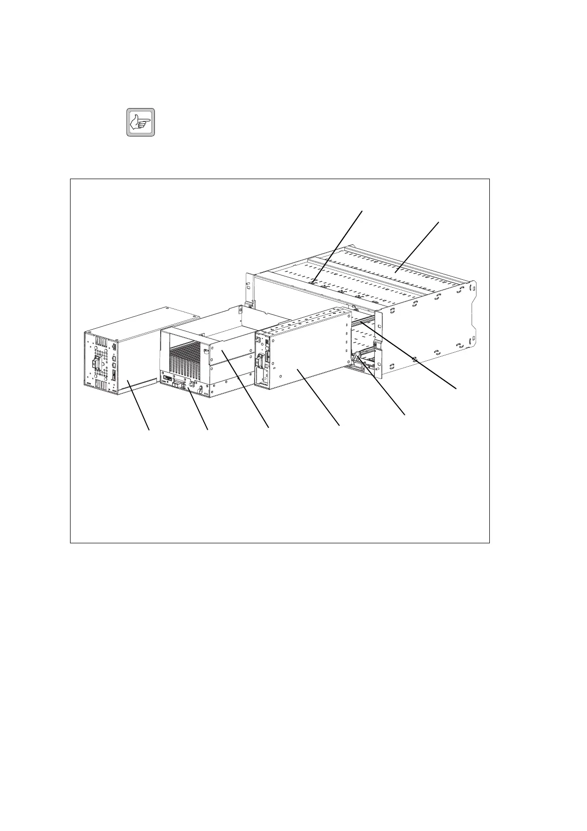
Figure 1.3 above shows the configuration for a typical single 100W base
station. The PMU occupies its normal slot at the left end of the subrack,
with the PA directly beside it. The single reciter occupies the slot
immediately to the right of the PA.
Unlike the 5W and 50W PAs, the 100W PA is mounted horizontally with
the heatsink facing upwards. It is also fitted with an airflow duct to channel
the airflow from the cooling fan through the heatsink fins.
Figure 1.3 Mechanical assembly - single 100W base station
b
PMU
f
module retaining clamp
c
PA
g
plastic guide rail
d
airflow duct
h
subrack
e
reciter
i
cable retaining clip
b
c
d
e
f
g
h
i

 Loading...


