T-K3 Service Manual
Ver. 1.05
17
CONFI DENTIAL
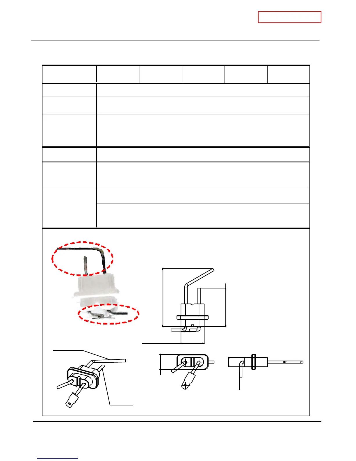
10-5. Flame rod
T-K3 Part # #716 Takagi Part # EKK0E Checkpoint
I
Function
Failure event
Effects on the T-K3
if flame rod fails
Error codes when
the flame rod fails.
111 121 721
D iagno stic
The flame rod is assembled with the AFR rod.
Orange(17) - Flam e r od
between the flame r od an d the
compute r boar d
Color/Number of
wires
1. Visual inspection: connection/breakage of wires or soot buildup on rod.
2. Check amperes: proper range of values shown below.
To dete ct flames whil e unit i s i n oper ation.
1 Unable to detect flames when flames actually do occur
2. Detecting a false flam e when no flames actua lly occur
1. The T-K3 stops operating. The "111" and/or "121" error code(s) will display
2. The T-K3 will not initiate the ignition proc ess. The "721" error code will display
(during combustion) 40KHz~60KHz
Orange(1 7) - Gr een(1 8)
(during combustion) 1
μ
A or more
1-3/8" (35mm)
5/8" (15mm)
7/8" (24mm)
3-1/2" (88.6mm)
2-1/4" (58.6mm)
AFR Ro d
Flame r od
Leads to computer board
Detecting elements (flame and AFR
 Loading...


