T-K3 Service Manual
Ver. 1.05
21
CONFI DENTIAL
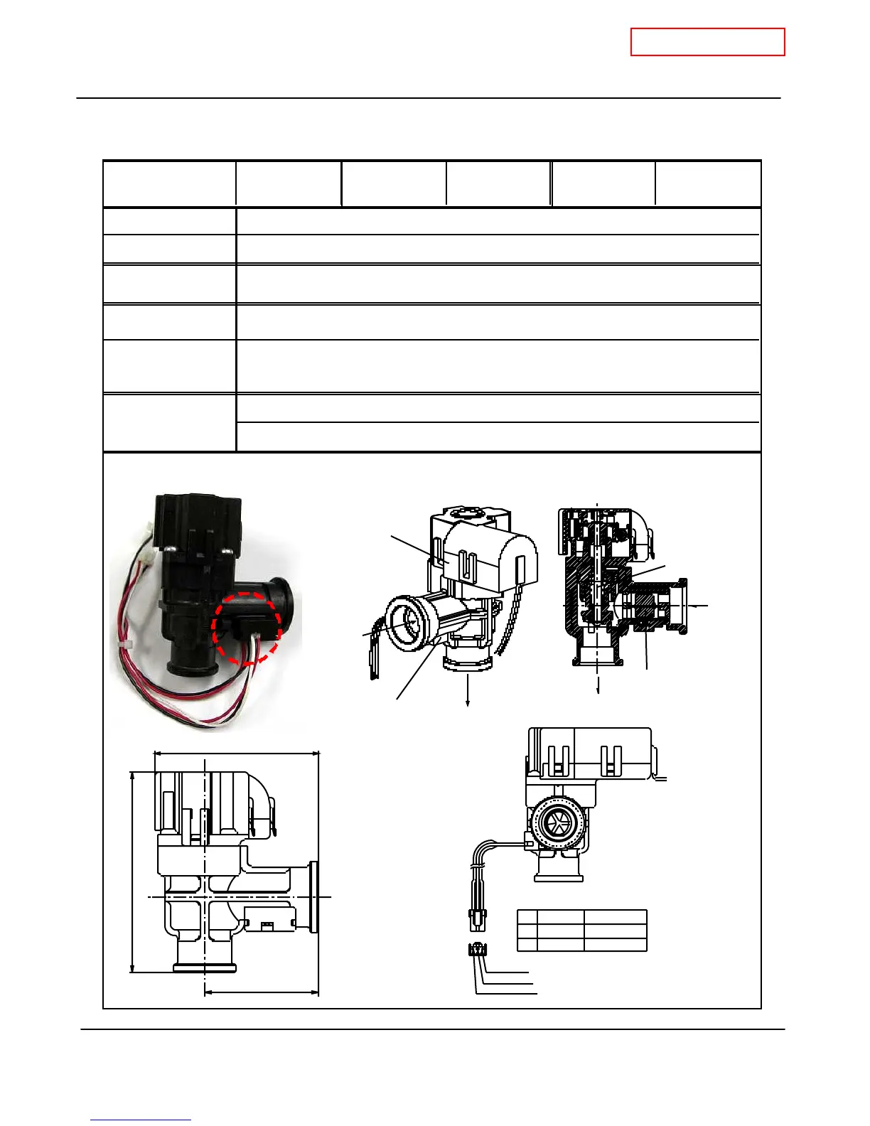
10-9. Flo w sensor
T-K3 Part # #402 Takagi Part # EKK0T Checkpoint
H2
Function
Failure event
Effects on the T-K3
if flow sensor fails
Error codes when
the flow sensor fails.
D iagnostic
Red-Black
W hite( 85) -Black
The flow sensor is assembled with the flow adjustment valve.
Detects and measures water flow rate using a spinning impeller and magnetic pick-
DC 4~5.5V (Input)
441 (only within multi-unit Easy-Link systems)
Color/Number of
wires
1. Visual inspection: connection/breakage of wires and/or debris on impeller
2. Check voltages: proper range of values shown below.
DC 1~4 V (p ulse) 1,080 pulse/m in (m or e tha n 1 8Hz)
Unable to detect or measure any water flow rate.
Ignition sequence does not start (T-K3 will not initiate any operation)
OUTPUT
VCC
GND
22
11
No.1
33
White
Black
Red
No.3
No.2
Flow sensor
>PPE-GF<
1-7/8" (47mm)
3-3/8" (84.4mm)
2-5/8" (67.5mm)
Flow sensor
IN
OUT
Flow
adjustment
valve
Flow sensor
Flow
adjustment
valve
Flow sensor
OUT
IN
 Loading...


