T-K3 Service Manual
Ver. 1.05
9
CONFI DENTIAL
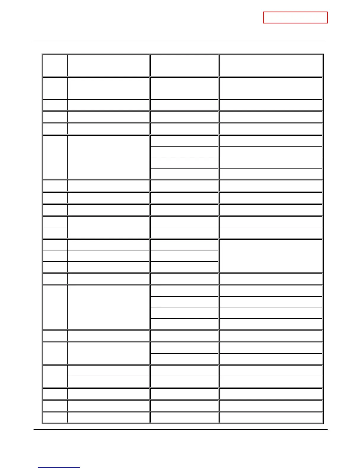
7. Wiring diagram check points for diagnosis
Check-
point
Part and Description Color of wires Normal range
A, A1 100V Power supply
Brown – Brown (A1)
White – Black (A)
AC 90~11 0 V
A2 120V Power supply Black - White AC 108~132V
B1 Heater Black - Black AC 90~11 0 V
B2 Igniter Purple - Purpl e AC 90~11 0 V
Light blue - blue at COM
DC 78~100V(in operation) / 0.9~1.3kΩ
Green - blue at COM
DC 78~100V(in operation) / 1.3~1.9kΩ
Orange - blue at COM
DC 78~100V(in operation) / 1.3~1.9kΩ
C Gas valves
Red - blue at COM
DC 78~100V(in operation) / 0.9~1.7kΩ
C Proportional Valve White - red at COM
DC 1~10V(in operation) / 30~51Ω
C1 Hi-limit switch Blue - Blue Less than DC 1V and less than 1.3Ω
C2 Overheat cutoff fuse Blue - Blue Less than DC 1V and less than 1.3Ω
D1 Black - White DC 15V (during Easy-Link operation)
D2
Easy link connectors
Black - White DC 15V
E1 Mixing thermistor Black - Black
E2 Outlet thermistor Black - Black
E3 Inlet thermistor Black - Black
See table on p. 10
F Remote controller * DC 11~25V
Red - Blue DC 110~160V
Yellow - Blue DC 13~17V
Orange - Blue DC 2~6.5V
G Fan motor
White - Blue See the “A
H1 Gas proportional valve White - red DC 1~10V and 30~50Ω
Red - Black DC 4~5.5V
H2 Flow sensor
White - Black DC 1~4V (1080pulse / min)
Air-fuel ratio flame rod Yellow - AFR rod More than 1μA (during burning)
I
Flame rod Orange - Flame rod More than 1μA (during burning)
J1 Flow adjustment valve Red - Black DC 7~16V and 0.09~0.2kΩ
J2 Bypass valve Red - Black DC 7~16V and 0.09~0.2kΩ
K Pump connector port White - Black Less than 1.3Ω
 Loading...


