T-K3 Service Manual
Ver. 1.05
7
CONFI DENTIAL
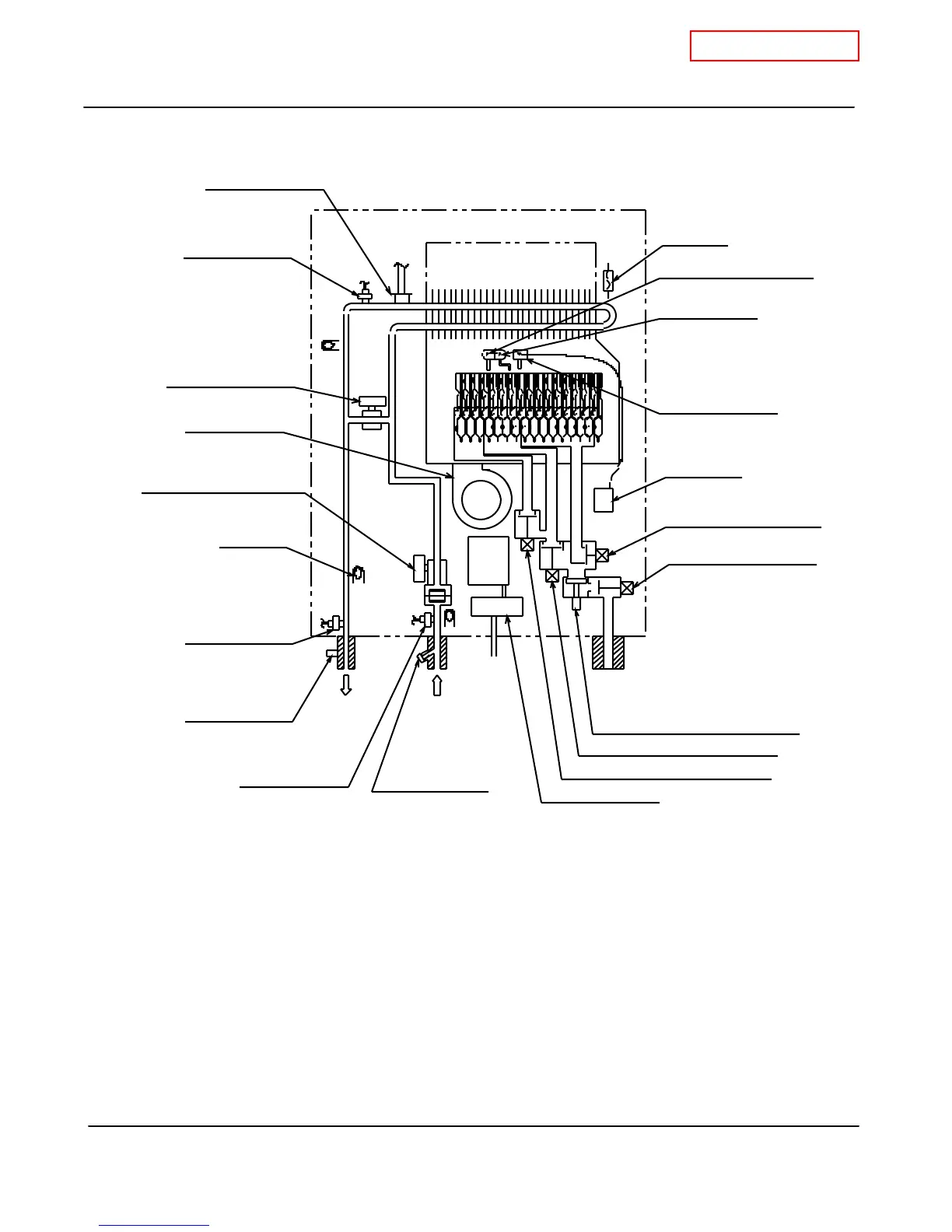
5. Schematic diagram
1. When a hot w ater tap is opened, cold w ater enters the T-K3 w ater heater.
2.
The w ater flow sensor detects this w ater flow and sends this information to computer.
3.
The computer initiates fan motor and sends signal to igniter to create ignition spark.
4.
The main, proportional, and solenoid gas valves open to allow gas input.
5.
The gas ignites and flames appear inside the burner chamber.
6.
Water circulates through the heat exchanger and is heated up to the set temperature.
7.
Using ther mistors to measure temperatures, the computer modulates the gas and w ater
valves to ensure proper output w ater temperatures.
8.
When the tap is closed, the T-K3 w ater heater shuts dow n.
H
O
T
C
O
L
D
G
A
S
PCB
Hi-limit SW
Inlet drain
plug filter
Mixing
Thermistor
Drain plug
Main gas valve
Gas solnoid valve 1
Fan motor
Flame rod
Igniter rod
Igniter
O.H.C.F
Heater
Flow adjustment valve
w/ Flow sensor
Gas proportional valve
Gas solenoid valve 3
Air-fu el ratio rod
Gas solenoid valve 2
Outlet
Thermistor
Bypass valve
Inlet
Thermistor
Transformer
 Loading...


