T-K3 Service Manual
Ver. 1.05
14
CONFI DENTIAL
10-2. Gas manifold
T-K3 Part # #103 Takagi Part # EKK1F Checkpoint
N/A
Function
Failure events
Effects on the T-K3
if the manifold fails.
Error codes when
the manifold fails.
D iagnostic
Color/Number of
wires
Blue -Red DC 78~100V / 0.9~1.7kΩ
1. Visual inspection: Excessive dust deposit around the nozzles or cracks on the
manifold.
2. Check voltages and resistance: proper range of values shown below.
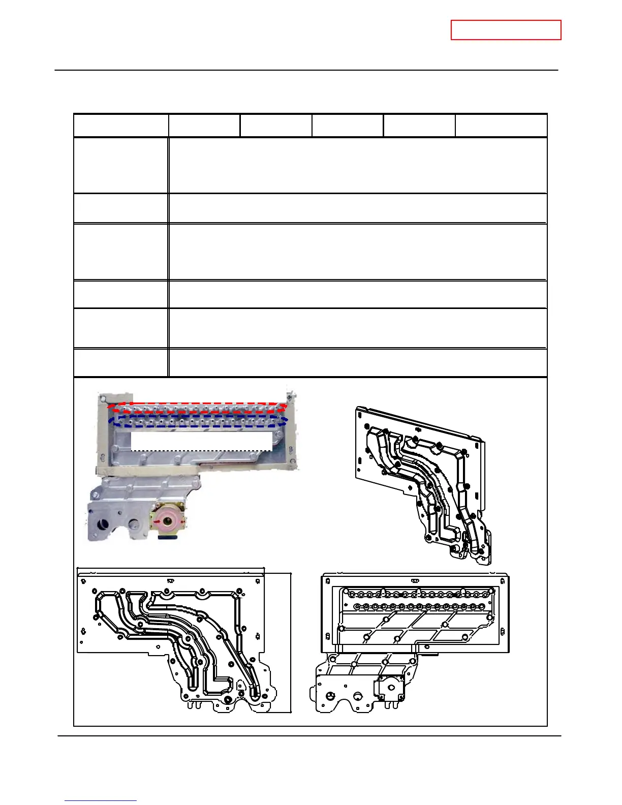
1. The manifold distributes gas from the gas valves to the burners. The manifold
has two types of the nozzles: on e type fo r gas-rich burne rs (1 6 no zzl es) and the
oth er for air -ri ch bu rners (1 5 n ozzles)
2. There are 3 zones within the manifold, to ensure efficient combustion operation.
1. Dust deposit on the manifold. 2. Gas leakage from a failed manifold.
3. Ignition failure. 4. Imperfect combustion.
1. Th e b urner s ca nn ot receive p roper gas flow fr om the manifold, which can cause
poor combustion in the combustion chamber. In this case, the AFR rod will detect
an improper flame condition and computer will take safety measures.
2. Gas leakage from the manifold.
111 121
9 -1/ 8" (23 2mm)
6-7/ 8" ( 175m m)
Nozzles for gas-rich burners
Nozzles for air-rich burners
 Loading...


