T-K3 Service Manual
Ver. 1.05
20
CONFI DENTIAL
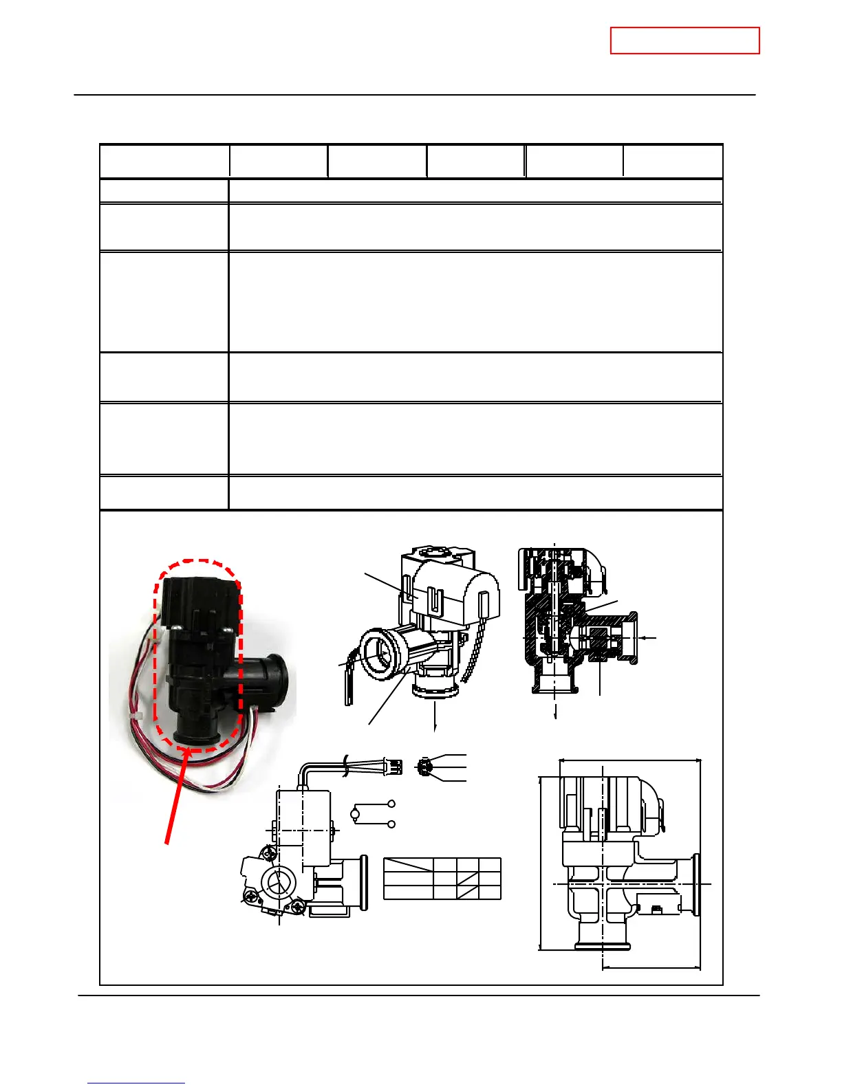
10-8. Flow adjustment valve
T-K3 Part # #402 Takagi Part # EKK0T Checkpoint J1
Function
F ailure event
Effects on the T-K3
if flow adjustment
valve
fails
Error codes when
F low Adjustment
Valve fails.
D iagnostic
Color/Number of
wires
Black-Red
The flow adjustment valve is assembled with the flow sensor.
1. Visual inspection: connection/breakage of wires, motor drive locked due to
scal e bu ildup , and/or water leak age.
2. Check voltages an d resistance ; proper range of val ues sh ow n be low .
DC7 ~16V and 0.0 9~0 .2kΩ
Controls water flow to properly control the output hot water temperaturet.
1. Water leakage from valve.
2. The valve cannot modulate or make open/close positions.
1. W ate r leakage fr om fa iled val ve can damage other T-K3 components.
2. Temper atur e fluctuations in the h ot wate r outp ut.
3. Within a multi-unit Easy-Link system, the "651" error code can occur.
651 (only within multi-unit Easy-Link systems)
Flow adjustment
valve
+ -
-+
132
Open
(Re d)
3
Close
(Bl ack)
1
M
No.
3
No. 2
No.
1
Flow
adjustment
valve
>PPE-GF<
1-7/8" (47mm)
3-3/8" (84.4mm)
2- 5/ 8" (6 7.5 mm )
IN
OUT
Flow
adjustment
valve
Flow sensor
Flow
adjustment
valve
Flow sensor
OUT
IN
 Loading...


