27
Models PH71/PH84 Operating Procedures
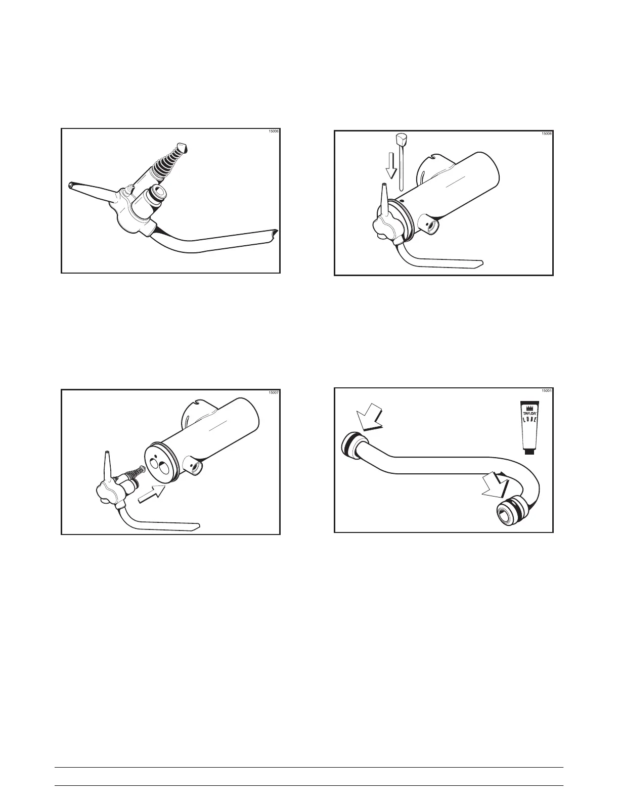
Attach the spring and poppet to the end of the pressure
relief fitting. The spring must be securely fastened and
not allowed to float freely.
Figure 24
Note: The spring and rubber poppet act as a pressure
relief valve to prevent a pressure build up in the
freezing cylinder.
Step 6
Insert the mix inlet tube assembly into the holes in the
base of the valve body.
Figure 25
Secure the pump parts in position by sliding the
retaining pin through the cross holes located at the
bottom of the pump cylinder .
Figure 26
Note: The head of the retaining pin should be facing
UP with the pump correctly installed.
Step 7
Install one o-ring on each end of the mix feed tube, and
thoroughly lubricate.
Figure 27