25
Models PH71/PH84 Operating Procedures
Step 7
Snap the design cap(s) over the bottom of the door
spout(s).
Step 8
Install the front drip tray and the splash shield under
the door spout(s).
Figure 16
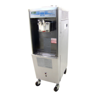
Step 9
Slide the long drip pan into the hole in the side panel.
Figure 17
Air/Mix Pump Assembly
The purpose of the air/mix pump is to meter a specific
amount of air and mix, and transfer this combination to
the freezing cylinder.
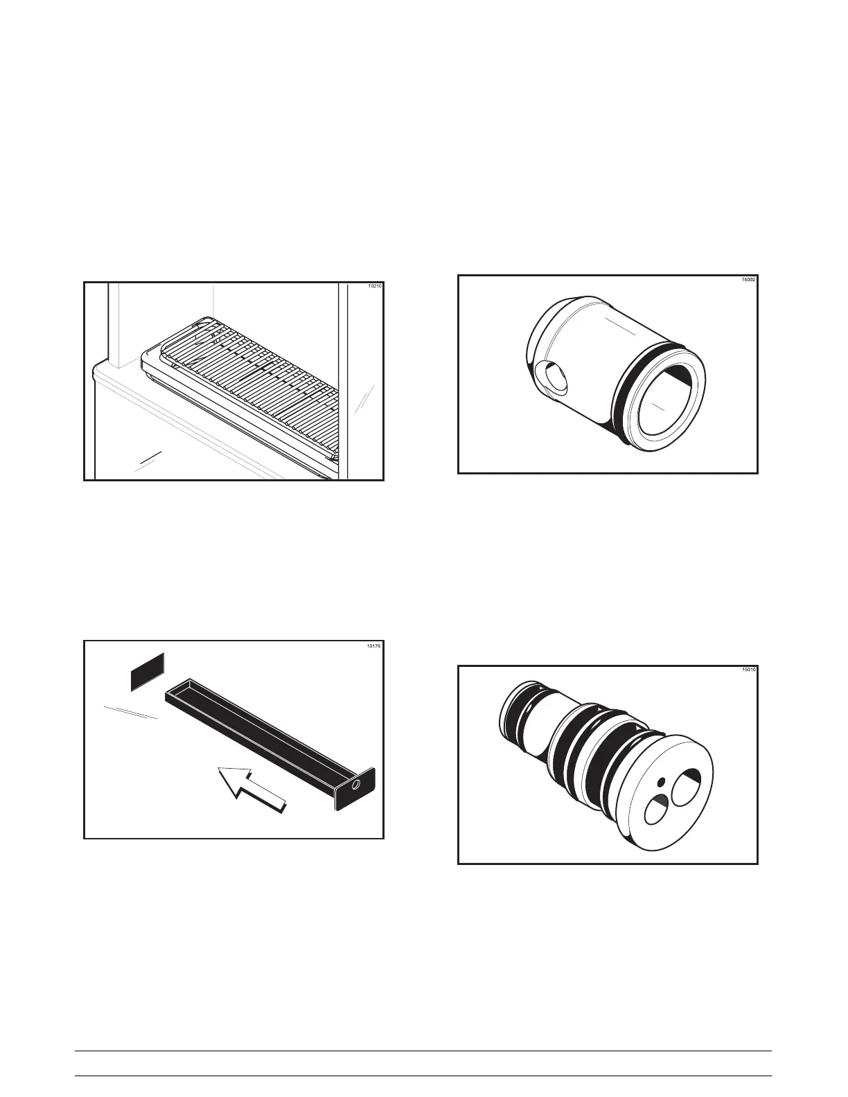
Step 1
Assemble the piston. Slide the o-ring into the groove
on the piston. DO NOT lubricate this o-ring.
Figure 18
Step 2
Assemble the valve body. Slide the three check rings
and three o-rings into the grooves on the valve body.
DO NOT lubricate the check rings or o-rings.
Note: Check rings have two smooth surfaces. A
concave shape indicates an incorrect assembly. Turn
the check ring inside out to correctly expose the flat
surface.
Figure 19