- 39 -
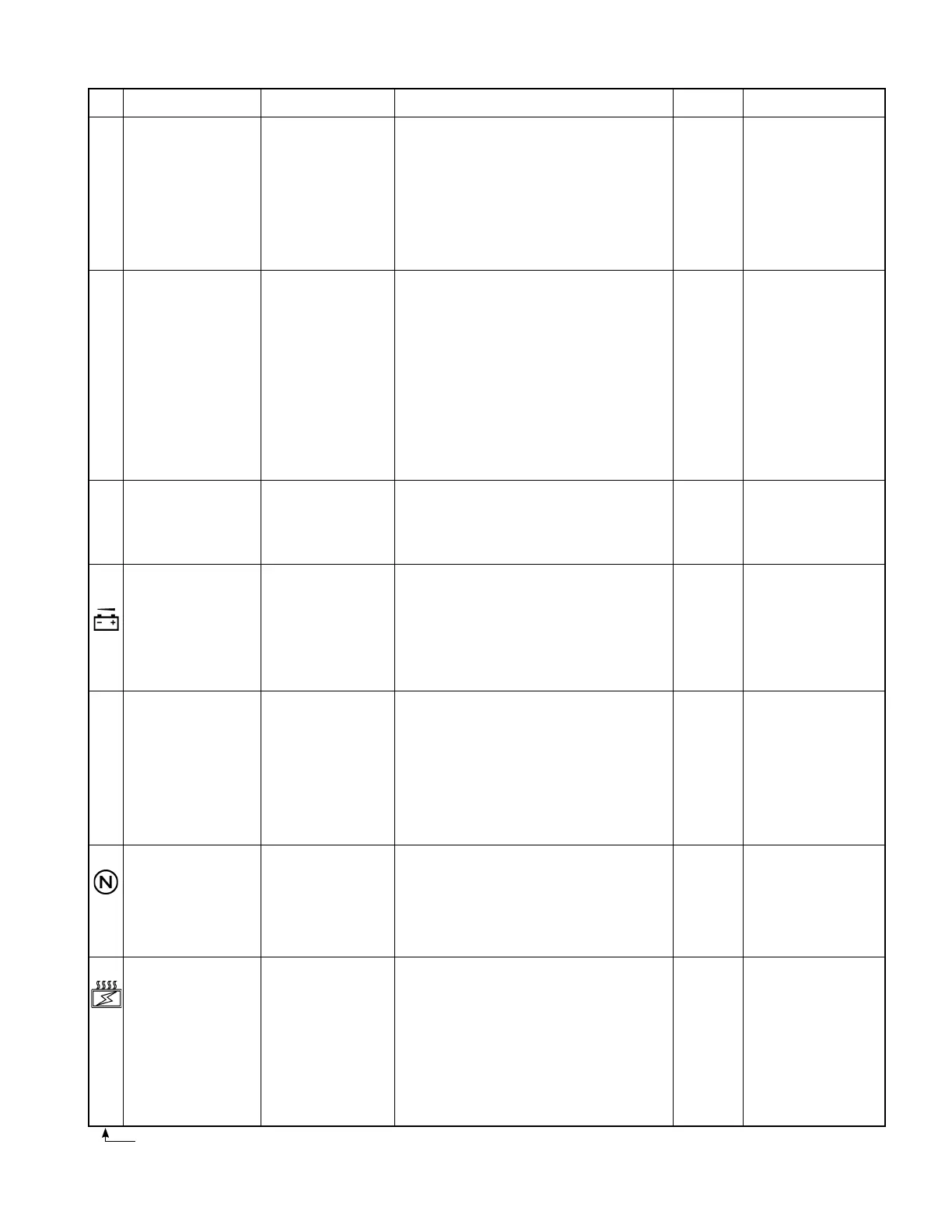
3. CONTROL SYSTEM
No.
17
[
301]
19
[
302]
20
[
307]
21
94
22
[
504]
23
24
Problem
Traveling accelerator
output defective
Output of traveling
current sensors (CSDU,
CSDW) is defective
Same circuit harness is
defective.
Traveling main fuse
(F1) blown out or sensor
circuit harness defective
Low voltage (low battery
voltage)
Traveling controller
thermo sensor (THD)
output defective
Traveling neutral
interlock detected.
* This error code might
also occur due to an
improper operation.
Traveling controller
temperature rises
abnormally.
Error
The truck won’t move.
The truck won’t move.
The truck won’t move
(MDcontactordoesnot
close)
Neither traveling or load
handling system won’t
work.(NeitherMDor
MPcontactordoesnot
close.)
Both systems work
when turning key switch
off and then on.
The truck runs
normally.
The truck won’t move.
The truck can move.
(This error is detected
when the traveling
controller temp. exceeds
110°C, and the current
is restricted to cause low
output.)
Remedy
Proceed with remedy in numerical order of encircled numbers.
①
Check harness between CN2-8, 9, 20 (CPU
board) and traveling accelerator, and repair or
change if needed.
②
Check traveling accelerator unit, and repair or
change if needed.
①
Check harness between CPU board and current
sensor, and repair or change if needed.
CSDU: CN5-3, 4, 14, 15
CSDW: CN5-5, 6, 16, 17
②
Check current sensor power supply voltage of
CPU board.
CSDU: between CN5-3 and 14, 15
CSDW: between CN5-5 and 16,17
If voltage is not normal, change CPU board.
③
Check current sensors (CSDU, CSDW), and
change if needed.
①
Check traveling fuse (F1) and change if needed.
②
Check harness between CN5-11 (CPU board)
and P2 terminal, and repair or change if needed.
③
Check harness between CN4-8 (CPU board)
and P1 terminal, and repair or change if needed.
①
Recharge battery.
②
Check harness between CN4-8 (CPU board)
and P1 terminal, and repair or change if needed.
①
Check thermo sensor (THD) voltage, and
change if needed.
②
Check harness between CN7-5, 11 (CPU board)
and thermo sensor (THD), and repair or change
if needed.
①
Operate the accelerator pedal and direction
switch properly.
②
Check accelerator and direction switch for
shorting, and repair or change if needed.
③
Check circuit connectors for looseness and
harness for any defect, and repair or change if
needed.
①
Cool down the controller.
②
CheckTMDU,TMDV,andTMDWforloose
ttingscrews.
③
Check the resistance/voltage of thermo sensor
(THD), and change the sensor, if needed.
④
Check harness between CN7-5, 11 (CPU board)
and thermo sensor (THD), and repair or change
if needed.
⑤
Check harness between CN9-6 (CPU board)
and CN1R-6 (power supply board), and repair
or change if needed.
Reset
Restore to
normal.
Turn off
key switch.
Turn off
key switch.
Turn off
key switch.
Restore to
normal.
Turn off
accelerator
and F/R
switch.
The
controller
will restore
to normal
when its
temperature
drops below
100°C.
Remarks
Accelerator power supply
voltage under normal
condition:
4.5 V (between CN2-9
and 20)
Accelerator output
voltage when an error is
detected:
over 3.3 V (between
CN2-8 and N terminal)
Sensor output under
normal condition:
• 3.0 - 11.0 V during
traveling
• about 7 V when F/R
switch is in neutral and
accelerator OFF
CSDU: between CN5-4
and 14, 15
CSDW between CN5-6
and 16, 17
Sensor power supply
voltage under normal
condition: 15 V
Check for secondary-side
voltage of fuse (F1).
This error is detected
when the battery voltage
is below 28 V (3 t: 42 V)
/ 0.8 seconds.
PS still works for
safety sake but is not
guaranteed.
Thermo sensor (THD)
voltage when an error is
sensed:
less than 0.2 V and more
than 4.95 V.
Thermo sensor resistance/
voltage under normal
condition:
20 kΩ/4.0 V at 25°C (±10
%)
Thermo sensor (THD)
voltage under normal
condition:
0.2 V to 4.95 V
The resistance/voltage
of thermo sensor under
normal condition:
20 kΩ/4.0 V (±10%) at
25°C
Numbers in brackets are error codes that appear on the meter panel.
 Loading...

