- 51 -
3. CONTROL SYSTEM
(3) Checking PS fuse (F3)
①
Set the tester to the voltage measurement range and attach the negative pole of the tester to the
negative cable connection terminal of the controller.
②
Attach the positive pole of the tester to the upper terminal of the F3 fuse and then to the lower
terminal to measure the voltage at each terminal.
Voltage table (key switch turned ON)
Location Voltage value Judgment
Upper terminal
Battery voltage Good
0 V Defective (change fuse)
Lower terminal Battery voltage Good
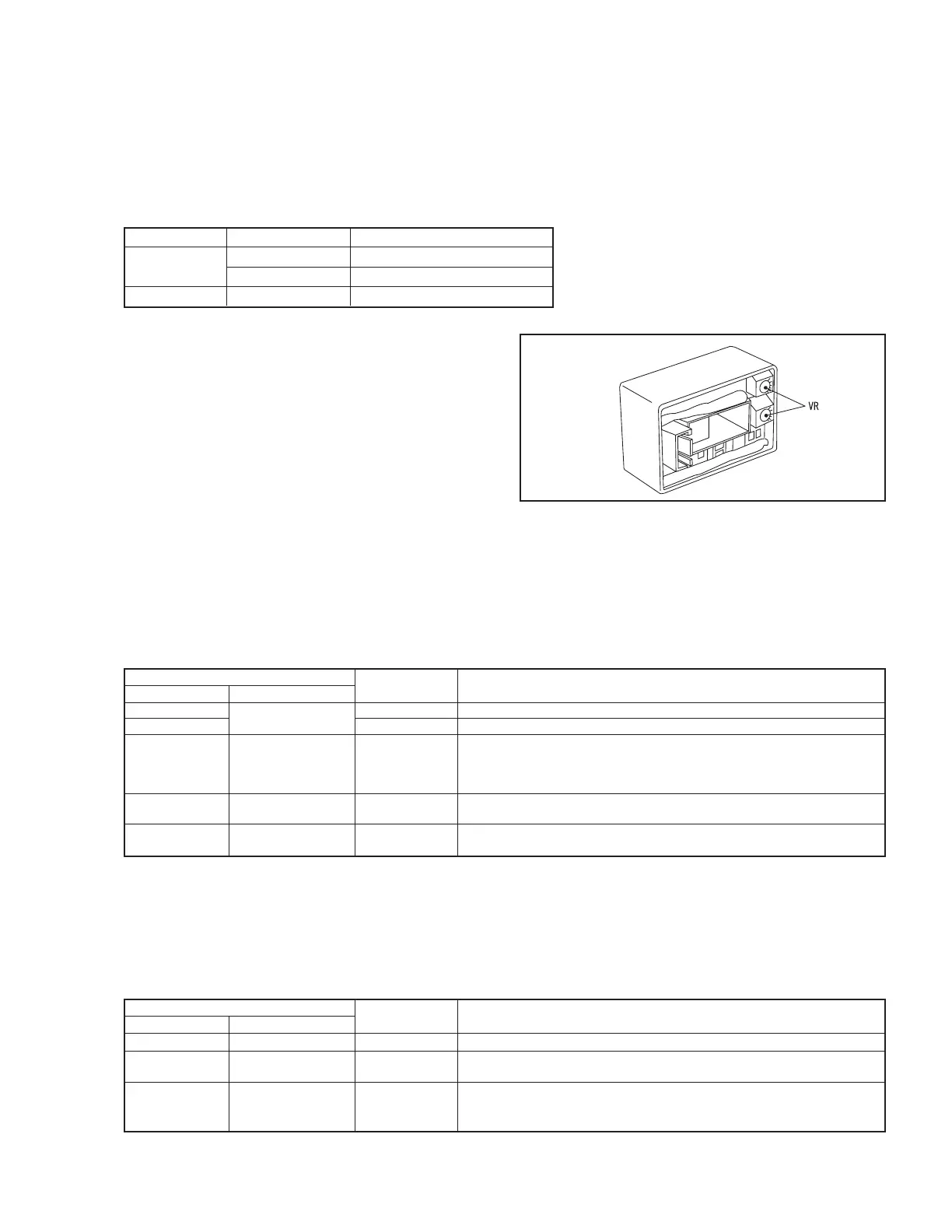
5. Checking current sensors
The current sensors detect the traveling U-phase
current, traveling W-phase current, and load handling
current and generate a voltage in proportion to each
electric current.
Before performing the following inspection,
visually check the sensors for scores, scratches,
damage or excessive discoloration. Do not touch the
current sensor VR.
(1) Checking traveling current sensors (CSDU, CSDW)
①
Set the tester to the voltage measurement range and attach the negative pole of the tester to the
negative cable connection terminal of the controller.
②
Attach the positive pole of the tester to each of the pins (3, 4, 5, 6, 14, 15, 16, and 17) of the CN5
(22-pin connector), and turn on the key switch to measure the voltage.
Voltage table (key switch turned ON)
Location Normal
Measurement condition
Pin No. Cable color voltage value
CN5-3
R-B (red - black)
15 V
CN5-5 15 V
CN5-14
CN5-15 GR (gray) 0 V
CN5-16
CN5-17
CN5-4 (CSDU) O (orange) 7 V (0 A)
F/R lever in neutral, accelerator OFF.
The voltage will vary within the range of 3 V - 11 V during traveling.
CN5-6 (CSDW) P (pink) 7 V (0 A)
F/R lever in neutral; accelerator OFF.
The voltage will vary within the range of 3 V - 11 V during traveling.
(2) Checking load handling sensor (CSP)
①
Set the tester to the voltage measurement range and attach the negative pole of the tester to the
negative cable connection terminal of the controller.
②
Attach the positive pole of the tester to each of the pins (7, 8, 18, and 19) of the CN5 (22-pin
connector), and turn on the key switch to measure the voltage.
Voltage table (key switch turned ON)
Location Normal
Measurement condition
Pin No. Cable color voltage value
CN5-7 R-B (red - black) 15 V
CN5-18
GR (gray) 0 V
CN5-19
F/R lever in neutral.
CN5-8 W (white) 7 V (0 A) The voltage will varies within the range of 7 - 9.35 V while the load
handling lever is actuated.
Fig. 3.10