3. CONTROL SYSTEM
- 52 -
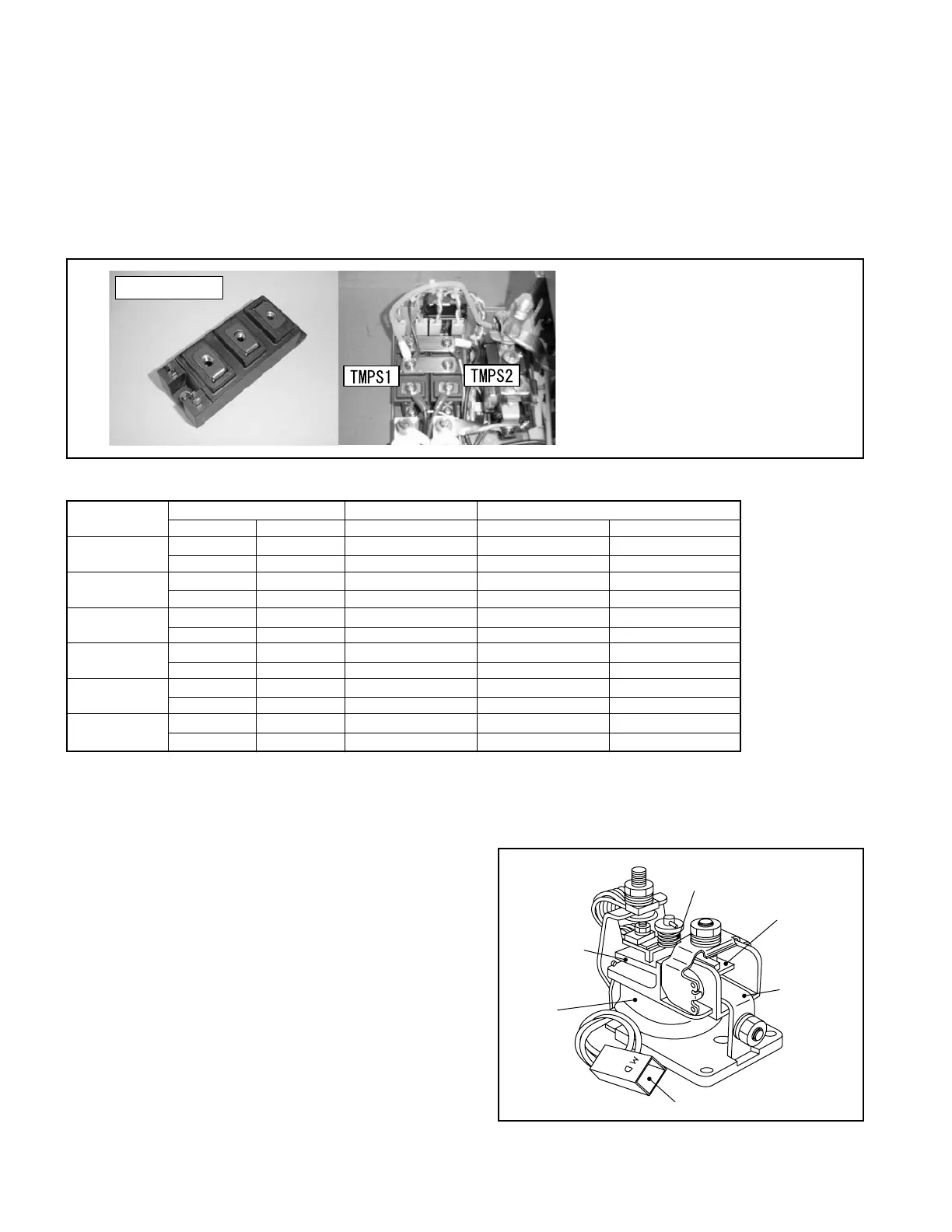
6. Checking PS transistors (TMPS1, TMPS2)
The PS drive transistors are two IGBT modules which form an H bridge.
①
Visually check the transistors for scores, scratches, damage, or excessive discoloration.
②
Remove all the cables from the module you are going to check, and measure the resistance between
terminals using the tester according to the table given below.
Use an analog tester set to a resistance range of 100 Ω.
③
Judgewhetherthetransistorisgoodordefectiveusingthemeasuredvalues.
7. Checking traveling/load handling/PS contactors (MD, MP, MPS)
(1) Checking mechanical movement of contactors
①
Inspection should be performed on each
contactor removed from the truck.
②
Push the movable contact with hand to conduct,
and check if it functions smoothly.
③
Push further after contacts are closed to check if
the compression spring is properly compressed
to press the contacts.
④
If any defect is found throughout the above
steps, replace the contactor with a new one.
Caution: Before installing an IGBT module,
apply silicone compound (Shietsu
Silicone G746 or equivalent) at the
rear side of the module.
ARMATURE
COIL
CONNECTOR
“a”
CONTACT
MOVABLE
CONTACT
COMPRESSION
SPRING
Location
Tester NormalvalueJudgment
(+) (–) Rough guide Good Not good
G1-C1
G1 C1 ∞Ω ∞Ω other than ∞Ω
C1 G1 ∞Ω ∞Ω other than ∞Ω
G1-E1
G1 E1 ∞Ω ∞Ω other than ∞Ω
E1 G1 ∞Ω ∞Ω other than ∞Ω
C1-E1
C1 E1 ∞Ω ∞Ω other than ∞Ω
E1 C1 approx. 700 Ω more than 1 Ω 0 Ω and ∞Ω
G2-C2
G2 C2 ∞Ω ∞Ω other than ∞Ω
C2 G2 ∞Ω ∞Ω other than ∞Ω
G2-E2
G2 E2 ∞Ω ∞Ω other than ∞Ω
E2 G2 ∞Ω ∞Ω other than ∞Ω
C2-E2
C2 E2 ∞Ω ∞Ω other than ∞Ω
E2 C2 approx. 700 Ω more than 1 Ω 0 Ω and ∞Ω
* The values given above should be used as rough guides. They will vary with different types of tester and the
internal battery’s state of charge.
Fig. 3.11
IGBT module