- 53 -
3. CONTROL SYSTEM
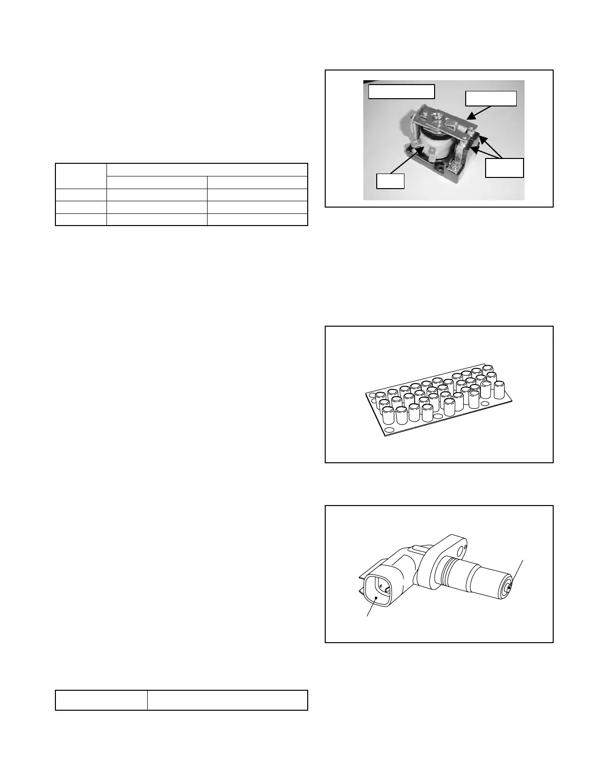
Fig. 3.13
Fig. 3.15
(2) Checking contactor coils
①
Remove the coil wiring connector.
②
Set the tester to a resistance range of 100 Ω and
measure the resistance between terminals using
the tester.
③
Judgewhetherthecoilisgoodornotusingthe
measured values.
Contactor
Judgment
Good Defective
MD 20-50Ω (typ, 30 Ω) ∞ Ω (broken coil)
MP 20-50Ω (typ, 30 Ω) ∞ Ω (broken coil)
MPS 120-380Ω (typ, 266 Ω) ∞ Ω (broken coil)
CONTACT
SENSOR
CONNECTOR
(3) Checking contactor contact points
①
Visually check the contactor contact points for roughness on the surface.
②
Replace any contactor with excessively rough or worn surface, with a new one.
8. Checking capacitor boards (CBD, CBP)
The capacitor board consists of multiple
aluminum electrolytic capacitors connected in
parallel,andinstalledjustabovetheFETpower
module. These capacitor boards absorb a surge
voltage generated from the FET power module to
prevent damage to the FET.
①
Visually check for scores, scratches or excessive
discoloration.
②
Replace any defective capacitor board with a
new one.
9. Checking motor speed sensor
The magnetic induction sensor is generates
alternating current per pitch of toothed rotor attached
to the side opposite the side to which the motor shaft
is directly connected.
Two magnetic induction sensors are used for the
traveling motor.
①
Remove the tester.
②
Set the tester to a resistance range of x 100
Ω and measure the resistance between sensor
terminals, using the tester.
③
Judgewhetherthesensor is goodornotusing
the measured values.
Normal value approx. 620 Ω (20°C)
MPS CONTACTOR
MOVABLE
CONTACT
COIL