84 Chapter 7 - Parameters Description User Manual
F.250 Ramp S-shape
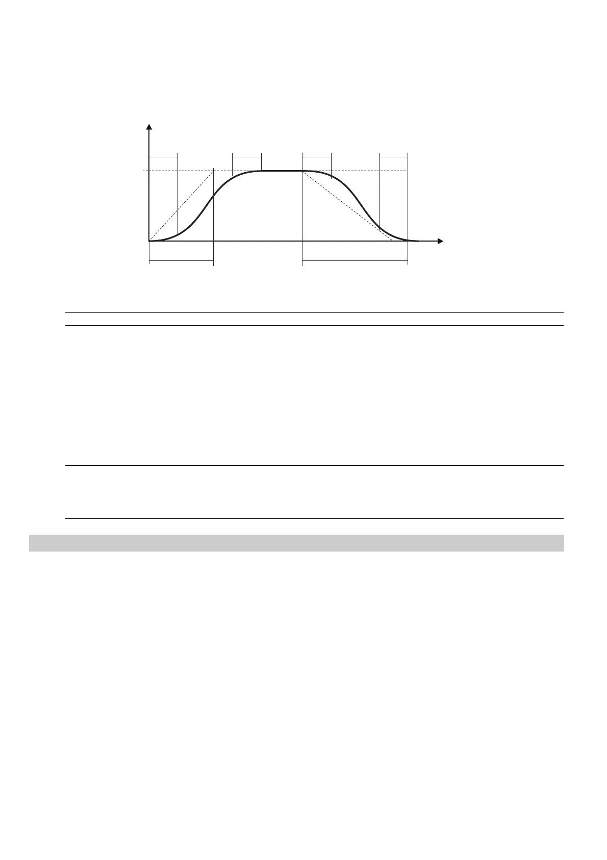
The S-shaped ramp can be useful to obtain a smooth behaviour of the system during the end of the acceleration
or close to the zero speed during the deceleration.
The value (in seconds) of the S-shaped ramp is added to the ramp time of the linear profile.
The ramp time is thus lengthened by the value of the S-curve constant.
F.250
F.250
F.250 F.250
f
t
ACC TIME DEC TIME
Figure 7.5.4: Ramp S-shape
Code Name [Code] & Function. Default MIN MAX Unit Variation IPA
F.250 Ramp S-shape 0 0 10 sec 0.1 337
F.260 Ramp extens src (Ramp extension source)
When an extension of the set ramps time is needed, it can be achieved through the Analog Inputs.
This extension will change linearly according to the value applied on the Analog Input.
The function allows the ramp times extension in a range includes between multiply factor 1 (0V, 0mA o 4mA)
and multiply factor 10 (+/-10V o 20mA).
The parameter select the source from where this function is provided and controlled.
Code Name [Code] & Function. Default MIN MAX Unit Variation IPA
F.260 Ramp extens src [0] Null 0 0 3 338
[1] Analog inp 1 (setting through I.200I.204)
[2] Analog inp 2 (setting through I.210I.214)
[3] Analog inp 3 (setting through I.220I.224)
Jump Frequencies
F.270 Jump amplitude
F.271 Jump frequency1
F.272 Jump frequency2
In a system composed by motor and drive, at certain frequencies values, it is possible to meet the generation of
noisy vibrations, characterized by mechanical resonances.
Through the parameters F. 2 71 and F.272 , it is possible to avoid the working of the inverter around the frequencies
here set.
The parameter F. 2 7 0 defines the tolerance band of the critical zone.