2. Connect the unit to an AC source as described in section 3.7.
3. Connect aDVM with appropriate cables for the rated voltage to the output terminals.
4. Turn the front panelAC power switch to On.
1. Turn on the output by pressing OUT pushbutton so the OUT LED illuminates.
2. Observe the power supply VOLT display and rotate the Voltage encoder. Ensure that the
output voltage varies while the VOLT encoder is rotated. The minimum control range is from
zero to the maximum rated output for the power supply model.
Compare the DVM reading with the front panel VOLT display to verify the accuracy of the
VOLT display. Ensure that the front panel VOLT LED is on.
3. Turn off the front panelAC power switch.
1. Ensure that the front panelAC power switch is at Off position and the DVM connected to the
output terminals shows zero voltage.
2. Connect aDC shunt across the output terminals. Ensure that the shunt and the wires' current
ratings are higher than the power supply rating. Connect a DVM to the shunt.
3. Turn the front panelAC power switch to On position.
4. Turn on the output by pressing OUT pushbutton so the OUT LED illuminates.
5. Observe the power supply CURRENT display and rotate the CURRENT encoder. Ensure that
the output current varies while the CURRENT encoder is rotated. The minimum control range
is from zero to the maximum rated output for the power supply model.
Compare the DVM reading with the front panel CURRENT display to verify the accuracy of
the CURRENT display. Ensure that the front panel CURRENT LED is on.
6. Turn off the front panelAC power switch.
7. Remove the shunt from the power supply output terminals.
Refer to Section 5.3 for explanation of the OVP function prior to performing the procedure below.
1. Turn the front panelAC power switch to On position and turn on the output by pressing OUT
pushbutton.
2. Using the VOLT encoder, adjust the output voltage to approx. 10% of the unit voltage rating.
3. Momentarily press
the OVP/UVL button so that the CURRENT display shows“OUP”. The
VOLTAGE display will show the last setting of the OVP level.
4. Rotate the VOLT encoder CCW to adjust the OVP setting to 50% of the unit voltage rating.
5. Wait a few seconds until the VOLT display returns to show the output voltage.
6. Adjust the output voltage toward it’smaximum and check that the output voltage cannot be
increased more than the OVP setting.
7. Adjust OVP limit to the maximum by repeating step 3 and rotating the VOLT encoder CW.
Refer to Section 5.4 for explanation of the UVL function prior to performing the procedure below.
1. Press the OVP/UVL button TWICEso that the CURRENT display shows"UUL". The VOLTAGE
display will show the last setting of the UVL level.
2. Rotate the VOLT encoder to adjust the UVL level to approx. 10% of the unit voltage rating.
3. Wait a few seconds until the VOLT display returns to show the output voltage.
4. Adjust the output voltage toward it’sminimum and check that the output voltage cannot be
decreased below the UVL setting.
5. Adjust the UVL limit to the minimum by repeating step1 and rotating the VOLT encoder CCW.
3.8.3 Constant Voltage Check
3.8.4 Constant Current Check
3.8.5 OVPCheck
3.8.6 UVLCheck
17
3.8 TURN-ON CHECKOUT PROCEDURE
3.8.1 General
The following procedure ensures that the power supply is operational and may be used as a basic
incoming inspection check. Refer to Fig.4-1 and Fig.4-2 for the location of the controls indicated in
the procedure.
3.8.2 Prior to Operation
1. Ensure that the power supply is configured to the default setting:
-AC On/Off switch at Off position.
-Dip switch :All positions at Down (”Off”) position.
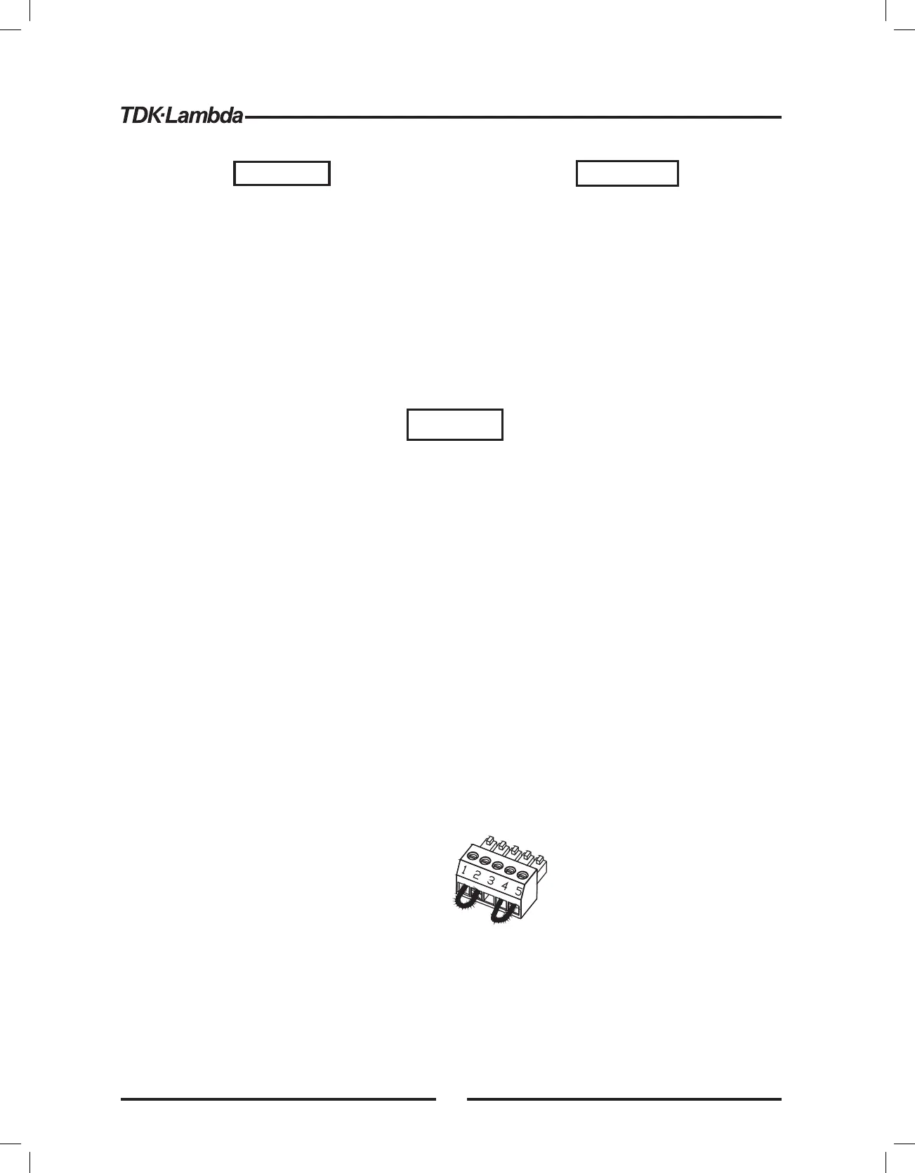
-Sense connector : Configured to Local Sense as shown in Fig.3-4:
1 Remote (+) sense
2 Local (+) sense
3 Not connected
4 Local (-) sense
5 Remote (-) sense
-For units equipped with IEEE option, ensure that the IEEE_En switch is in Up (default) position
(Refer to Fig.4-2, item 8 for location), if checkout is to be done in IEEE mode.
Fig.3-4: Sense connector default connection
Plug P/N: MC 1.5/5-ST-3.81
(Phoenix)
3.7.1 AC Input Connector
An IEC connector is provided on the rear panel for connecting the unit to the AC power source with
an AC cord. The IEC connector also provides the safety ground connection while the AC cord is
plugged into an appropriate AC receptacle.
3.7.2 AC Input Cord
Refer to section 1.3.4 for details of theAC input cords recommended for the GENH750W models.
WARNING
The AC input cord is the disconnect device of the power
supply. The plug must be readily identifiable and accessible to
the user. The AC input cord must be no longer than 3m.
WARNING
WARNUNG
Some components inside the power supply
are at voltage even when the On/OffAC
switch is in the “Off ” position. To avoid electric
shock hazard, disconnect the line cord and
load and wait two minutes before removing
cover.
Einige Komponenten innerhalb des Netzteils
f hren Netzspannung, selbst wenn derü
On/Off-Schalter in der Position “Off” steht. Um
die Gefahr eines elektrischen Schlags zu
vermeiden, trennen Sie es vom Netz und
warten Sie zwei Minuten, bevor Sie die
Abdeckung entfernen.
16