5.4 UNDER VOLTAGE LIMIT (UVL)
5.5 FOLDBACKPROTECTION
5.6 OUTPUT ON/OFF CONTROL
5.7 OUTPUT SHUT-OFF (SO) CONTROL VIA REAR PANEL J1 CONNECTOR
The UVL prevents adjustment of the output voltage below a certain limit.The combination of UVL
and OVP functions, allow the user to create a protection window for sensitive load circuitry.
Setting the UVL can be made when the power supply output is Enabled (On) or Disabled (Off). To set
the UVL level, press the OVP/UVL button TWICE, so that the CURRENT meter shows “UUL”. The
VOLTAGE meter shows the UVL setting level. Rotate the VOLTAGE encoder knob to adjust the UVL
level. The display will show “UUL” and the setting value for 5 seconds after the adjustment has been
completed and then will return to it’s previous state.
UVL setting values are limited at the maximum level to approximately 95% of the Output Voltage
setting. Attempting to adjust the UVL above this limit will result in no response to the adjustment
attempt. The minimum UVL setting is zero.
5.4.1 Setting the UVL level
Foldback protection will shut down the power supply output if the load current exceeds the current limit
setting level. This protection is useful when the load circuitry is sensitive to an over current condition.
To arm the Foldback protection, the FOLD button should be pressed so that the FOLDLED illuminates.
In this condition, transition from Constant Voltage to Constant Current mode will activate the Foldback
protection. Activation of the Foldback protection disables the power supply output, causes the ALARM
LEDto blink and display "Fb" on the VOLTAGE meter.
There are four methods to reset an activated Foldback protection.
1. Press the OUT button. The power supply output is enabled and the Output Voltage and current
will return to their last setting. In this method, the Foldback protection remains armed, therefore if
the load current is higher than the current limit setting, the Foldback protection will be activated
again.
2. Press the FOLD button to cancel the Foldback protection. The power supply output will be disabled
and the VOLTAGE display will show “OFF”.Press the OUT button to enable the power supply output.
3. Turn the power supply output Off and then On using the SO control (refer to sect. 5.7). In this method
the foldback protection remains armed, therefore if the load current is higher than the current limit
setting the Foldback protection will be activated.
4. Turn the power supply Off using the AC On/Off switch, wait until the front panel display turns Off,
then turn the unit back ON again. The power supply output is enabled and the Output Voltage and
Current will return to their last setting. In this method, the Foldback protection remains armed,
therefore if the load current is higher than the current limit setting, the Foldback protection will be
activated again.
TheOutput On/Off enables or disables the power supply output. Use this function to make adjustments
to either the power supply or the load without shutting off the AC power.The Output On/Off can be
activated from the front panel using the OUT button or from the rear panel J1 connector.The OUT
button can be pressed at any timeto enable or disable the power supply output. When the output is
disabled, the output voltage and current fall to zero and the VOLTAGE display shows“OFF”.
Contacts 2,3 and 15 of J1 (Fig.4-2, Item 5) serve as Output Shut-Off (SO) terminals. The SO terminals
accept a 2.5V to 15V signal or Open-Short contact to disable or enable the power supply output. The
SO function will be activated only when a transition from On to Offis detected after applying AC power
to unit. (Thus ,inAuto-Restart mode, the output will be enabled after applying AC power, even if SO is in
Off level.). After On to Off transition is detected, the SO will enable or disable the power supply output
according to the signal level or the short/open applied to J1. This function is useful for connecting power
supplies ina“Daisy-chain” (refer to section 5.16). TheSO control can be used also to reset the OVP
and Fold Protection. Refer to sect. 5.3 and 5.5 for details.
5.5.1 Settingthe Foldback protection
5.5.2 Resetting activated Foldback protection
36
When the unit is shut-off by J1 signal, the VOLTAGE display will show “SO” to indicate the unit state. J1
contact 15 is the SO signal input and contacts 2 and 3, IF_COM, are the signal return (connected
internally). Contacts 2,3 and 15 are optically isolated from the power supply output.
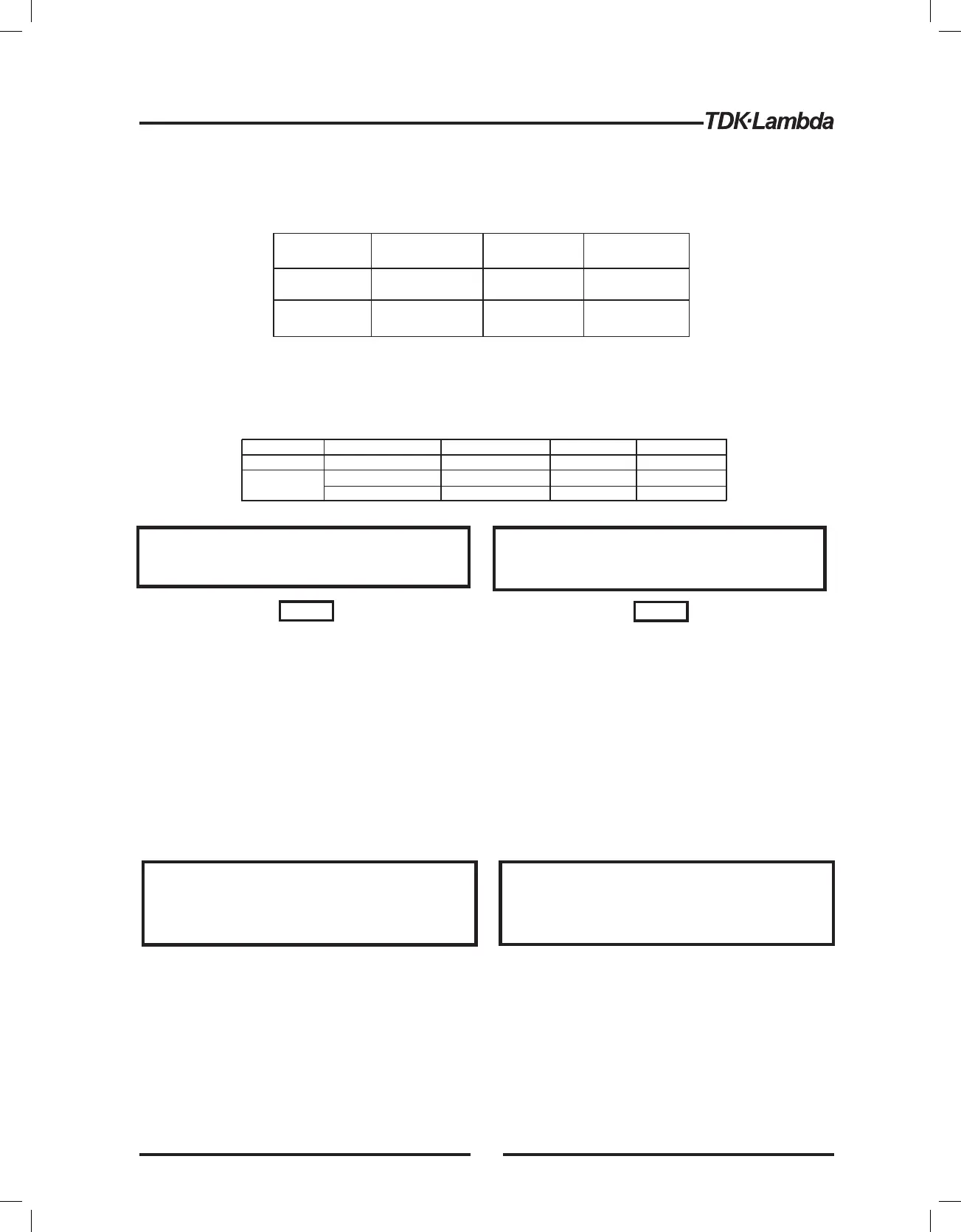
The SO control logic can be selected by the rear panel SW1 Setup switch. Refer to Table 5-2 for SW1
setting and SO control logic.
Table 5-2: SO logic selection
SW1-5 setting
Down (default)
Up
SO signal level
J1-2(3), 15
2-15V or Open
0-0.6V or Short
2-15V or Open
0-0.6V or Short
Power supply
output
On
Off
Off
On
Display
Voltage/Current
“SO”
“SO”
Voltage/Current
5.8 ENABLE/DISABLE CONTROL VIA REAR PANEL J1 CONNECTOR
Contacts 1 and 14 of J1 (Fig.4-2, Item 5) serve as Output Enable/Disable terminals by switch or relay.
This function is enabled or disabled by the SW1 Setup switch position 9. Refer to Table 5-3 for
Enable/Disable function and SW1 setting.
Table 5-3: Enable/Disable function and SW1 setting
SW1-9 setting
Down (Default)
Enable/Disable inputs
Open or Short
Open
Short
Power supply output
On
Off
On
Display
Voltage/Current
“ENA”
Voltage/Current
ALARM LED
Off
Blinking
Off
Up
5.9 CV/CC SIGNAL
5.10 PS_OK SIGNAL
CV/CC signal indicates the operating mode of the power supply, Constant Voltage or Constant Current.
CV/CC signal is an open collector output with a 30V parallel zener, at J1-13, referenced to the COM
potential at J1-12 (connected internally to the negative sense potential). When the power supply
operates in Constant Voltage mode, CV/CC output is open. When the power supply operates in Constant
Current mode, CV/CC signal output is low(0-0.6), with maximum 10mAsink current.
PS_OK signal indicates fault condition in the power supply. PS_OK is a TTL signal output at J1-16,
referenced to IF_COM at J1-2,3 (Isolated Interface Common)). When a fault condition occurs, PS_OK
level is low, with maximum sink current of 1mA, when no fault condition occurs, PS_OK level is high with
maximum source current of 2mA. The following faults will set the PS_OK to Fault state:
Safe Start mode
Auto Restart mode
-If the Enable/Disable fault condition
clears when units in safe start mode recovery is by
pressing OUT button or by sending a ‘OUT 1’ serial
command.
- The output will return back ON
automatically when the Enable/Disable fault conditions
clears.
To prevent possible damage to the unit, do not connect
any of the Enable/Disable inputs to the positive or
negative output potential.
NOTE: After auto restart setting, you have to set output stage to "ON output" (OUT LED is lightening), to complete and
relese auto restart mode change.
CAUTION
VORSICHT
Um das Gerät vor möglichen Schäden zu schützen,
verbinden Sie nie einen der Enable/Disable-Eingänge
mit dem Plus- oder Minus-Ausgangspotential.
Safe-Start-Modus - Im Safe-Start-Modus kehrt das
Netzteil erst dann in den Normalbetrieb zurück, wenn der
Enable/Disable-Eingang aktiviert wurde und zusätzlich die
OUT - Taste betätigt wird oder das Gerät ein "OUT1
“-Kommando über die serielle Schnittstelle empfängt.
- In diesem Modus kehrt das
Netzteil automatisch in den Normalbetrieb zurück, sobald
der Enable/Disable-Eingang aktiviert wurde.
Auto-Restart-Modus
HINWEIS
NOTE
Do not connect CV/CC signal to a voltage source
higher than 30VDC. Always connect CV/CC signal to
the voltage source with a series resistor to limit the
sink current to less than 10mA.
CAUTION
VORSICHT
Verbinden Sie den CV/CC-Ausgang nur mit einer
Spannungsquelle bis maximal 30V DC. Verbinden Sie
den Anschluss stets über einen Vorwiderstand mit der
Spannungsquelle, oder begrenzen Sie den Strom auf
andere Weise auf max. 10 mA.
*OTP
*OVP
*Foldback
*AC fail
*Enable/Disable open (Power supply is disabled)
*SO (Rear panel Shut-Off - Power supply is shut off))
*IEEE failure (with optional IEEE interface)
*Output Off
37