CHAPTER 4FRONT AND REAR PANEL CONTROLS
AND CONNECTORS
4.1INTRODUCTION
4.2FRONT PANEL CONTROLS AND INDICATORS
The Genesys Power Supplyseries has afullset of controls, indicators and connectors that allow
theuserto easily setupand operate the unit. Beforestartingto operate the unit, please readthe
following sections forexplanationofthe functions of the controls andconnectors terminals.
- Section4.2:Front panel controls andindicators.
- Section4.3: Rear panel controls and connectors.
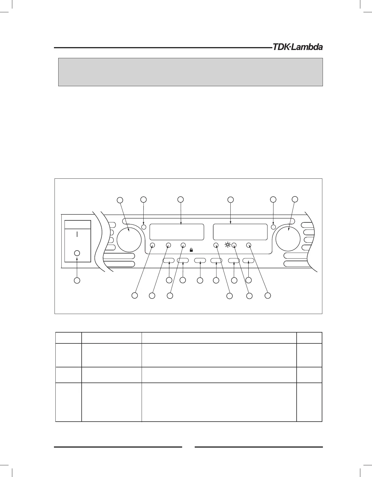
See Fig.4- 1toreviewthe controls, indicators and meters located on the powersupply front panel.
TM
Fig.4-1: Front panel controls and indicators
1
Number
Control/Indicator
Description
Section
High resolutionrotary encoder foradjusting the Output
Voltage. Also adjuststhe OVP/UVL levels and selects
theAddress.
VOLTAGE control
VOLTAGE indicator
Green LED,lightsfor Constant-Voltage mode
operation.
2
3
VOLTAGE display
4digit, 7-segment LED display.Normally displays the
output voltage. When the PREV buttonispressed, the
displayindicatesthe programmed settingofthe output
voltage. When the OVP/UVL buttonispressed,the
Voltage displayindicatesthe OVP/UVL setting.
Table4-1:Front Panel controls and indicators
VOLTAGE
ALARM
FINE
PREV/
OVP
UVL
FOLD
REM/LOC
OUT
DC AMPS
CURRENT
'
'
'
'
'
'
'
'
DC VOLTS
POWER
1
14
17
18
19
2
15
16
3
13
10
4
11
5
12
9
6
7
8
5.2.1
5.3.1
5.4.1
7.2.2
27