16
Number Control/Indicator Description
Section
FINE button
18
ALARM indicator
Table4-1:Front Panel controls and indicators
17
FINE indicator
AC Power switch
19
Voltage and Current Fine/Coarse adjustment control.
Operates asatoggleswitch.InFine mode,the
VOLTAGE and CURRENT encoders operatewith high
resolution and in Coarse mode with lower resolution
(approx.6turns).
:Advanced Parallel Operation
Mode setting.
Auxiliary function
Green LED, lights when the unitisinFine mode.
Red LED, blinks in case of fault detection. OVP, OTP
Foldback, Enable and AC fail detectionwill cause the
ALARM LED to blink.
AC On/Off control.
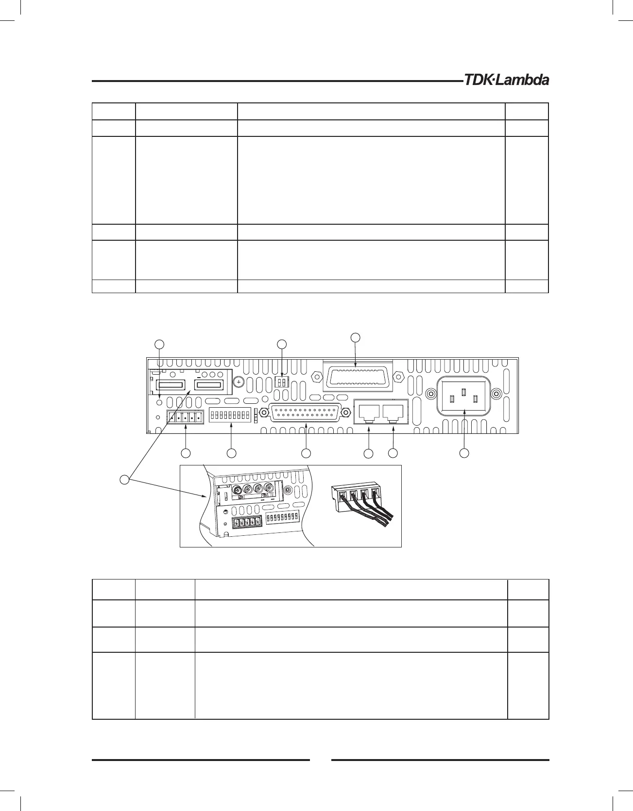
4.3 REAR PANEL
See Fig.4-2toreview the connections and controls located on the power supplyrear panel.
Refer to Table4-2 for explanations about therear panel connections and controls.
Fig.4-2: Rear panel connections and controls
1
Number
Item
Description
Section
AC input
connector
2
DC output
Table4-2: Rear panel connections and controls
3
IEC connector
3.7.1
Bus-barsfor 6V to 60V models.
Wire clamp connector for 80V to 600V models.
3.9.6
RJ-45 typeconnector, usefor connectingpower supplies to
RS232 or RS485 port of computer for remotecontrol purposes.
When usingseveral powersupplies inapower system, the first
unit Remote-In is connectedtothe computerand theremaining
units arechained, Remote-In to Remote-Out.
Remote-In
connector
7.3
7.4
Green LED, lights when PREV buttonispressed.
PREV indicator
15
5
6
2
8
9
7
4
3
1
80~600V
Models
6~60V
Models
10
+
VDC
+
+
5.15.2
4
Number Control/Indicator Description
Section
4 digit, 7-segment LED display.Normally displays the
output current. When the PREV button is pressed, the
display indicates the programmed setting of output
current.
CURRENT display
6
CURRENT control
High resolution rotary encoder for adjusting the Output
Current. Also selects the Baud-Rate of the
communication port.
Table 4-1: Front Panel controls and indicators
5
CURRENT indicator
Green LED, lights for Constant-Current mode operation.
Main function
Auxiliary function
:Output ON/OFF control. Press OUT to
set the output On or Off. Press to reset and turn On the
output after OVPorFOLD alarm events have occurred.
: Selects between "Safe-Start" and
"Auto-Restart" modes. Press and hold OUT button to
toggle between "Safe-Start" and "Auto-Restart".The
VOLT display will cycle between "SAF" and "AU7”.
Releasing the OUT button while one of the modes is
displayed, selects that mode.
OUT button
OUT indicator
28
Green LED, lights when Foldback protection is On.
Over Voltage Protection and Under Voltage limit setting.
- Press once to set OVP using VOLTAGE encoder ( the
current display shows“OUP” )
- Press again to set the UVL using VOLTAGE encoder
( the current display shows “UUL” ).
Main function
Auxiliary function
:Goto local. Press REM/LOCto put the
unit into Local (REM/LOC button is disabled at Local
Lockout mode).
: Address and Baud Rate setting.
Press and hold REM/LOC for 3sec. to set the Address
with the VOLTAGE encoder and the Baud Rate with the
CURRENT encoder.
Green LED, lights when the unit is in Remote mode.
Foldback protection control.
- Press FOLD to set Foldback protection to On.
-To release Foldback alarm event, press OUT to
enable the output and re-arm the protection.
- Press FOLD again to cancel the Foldback protection.
Main function
Auxiliary function
: Press PREV to display the output
voltage and current limit setting. For5sec. the display
will show the setting and then it will return to show the
actual output voltage and current.
: Front Panel Lock. Press and hold
PREV button to toggle between “Locked front panel”
and “Unlocked front panel”. The display will cycle
between “LFP” and “UFP”. Releasing
the PREV button
while one of the modes is displayed, selects that mode.
REM/LOC button
REM/LOC indicator
FOLD button
FOLD indicator
OVP/UVL button
PREV/ button
Green LED, lights when the DC output is enabled.
7
8
9
10
11
12
13
14
5.2.2
7.2.4
5.6
7.2.5
5.11
7.2.2
7.2.4
5.5
5.3
5.4
5.17
29