30
Table4-2: Rear panel connections and controls
RJ-45 type connector, used for chaining power suppliestoform
a serial communication bus.
Connector forremote analog interface. Includes output voltage and
current limit programming and monitoringsignals, Shut-off control
(electrical signal), Enable/Disable control(dry-contact), power
supplyok(PS_OK) signal and operation mode (CV/CC) signal.
Nine positionDIP switch forselecting remote programming and
monitoring modes for Output Voltage, Current Limit and other
controlfunctions.
Blank sub-platefor standard units. Isolated Remote Analog
programming connector for units equipped with Isolated
Analog control option. IEEE connectorfor units equipped with
IEEE programming option (shown).
M4x8 screw for chassisground connection.
Two positionDIP switchfor selectingIEEE mode or RS232/485
mode when IEEE optionisinstalled.
Number
Item
Description
Section
4.5
Connectorfor makingremotesensing connections to theload
forregulationofthe load voltage and compensationof load
wire drop.
4.4
4.4.1
4.4.2
3.8.2
3.10.2
3.10.3
4
5
6
7
8
10
9
Remote Out
connector
Programming
and
Monitoring
connector
SW1 Setup
switch
Remote
sense
connector
Blank
Sub-plate
Ground
screw
IEEE
switch
7.3
7.4
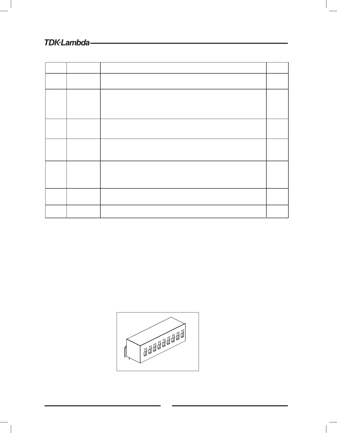
4.4 REAR PANEL SW1 SETUP SWITCH
The SW1 Setup switch(see Fig.4-3) isa9-positionDIP switchthat allows the user to choose the
following:
-Internal or remoteprogramming for Output Voltage and Current Limit.
- Remote voltage or resistiveprogramming of Output Voltage and Output Current limit.
- Select range of remote voltage and resistiveprogramming.
- Select range of Output Voltage and Output Current monitoring.
- Select the Remote Shut-Off controllogic.
- Select between RS232 or RS485 communicationinterface.
- Enableordisablethe rear panel Enable/Disable control(dry contact).
Fig.4-3: SW1 setup DIP switch
1
2
3
4
5
6
7
8
9
30