Load lines, twisted pair,
shortest length possible.
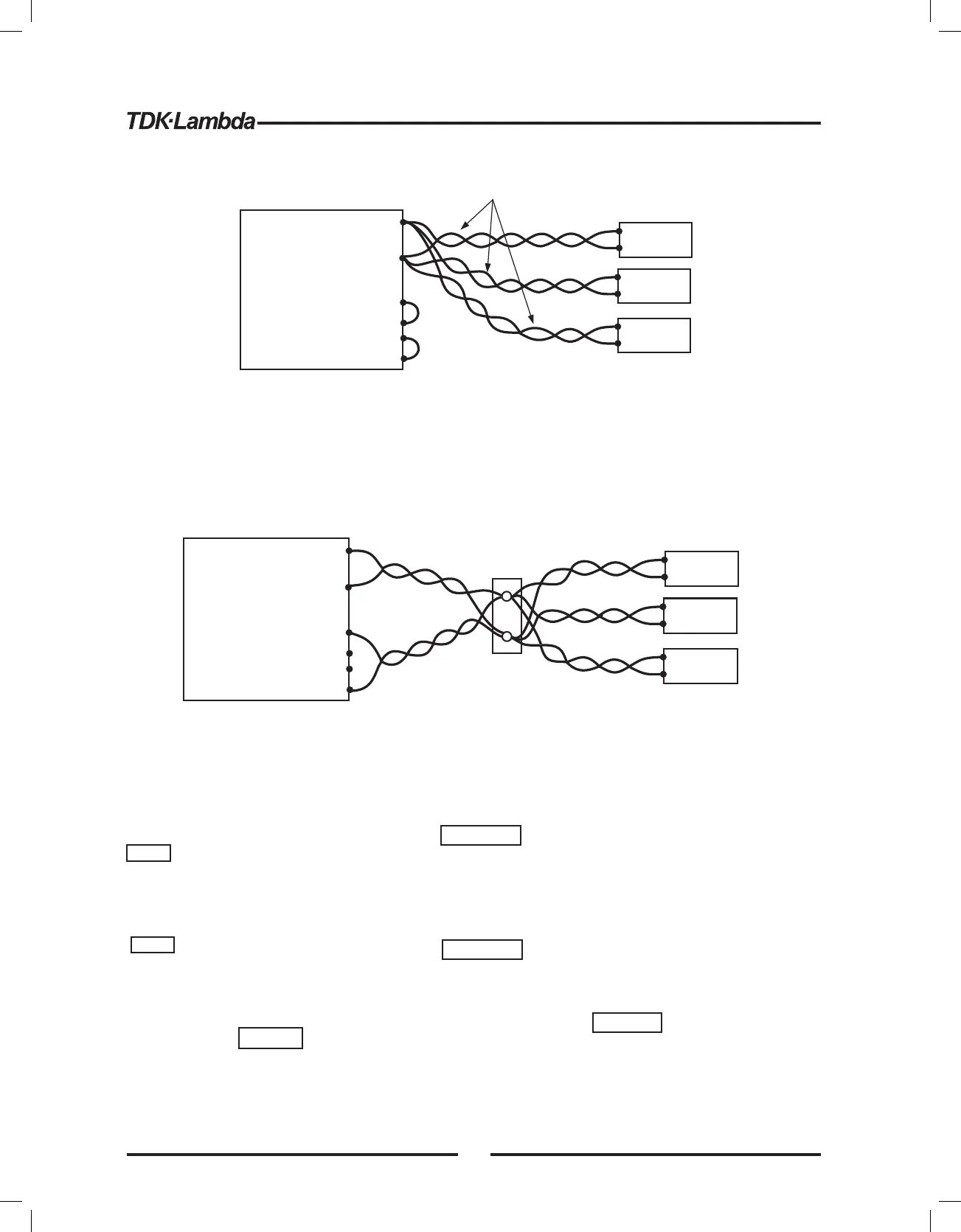
Fig.3-12: Multiple loads connection, radial distribution, local sense
-Rem.sense
-Local sense
+Local sense
+Rem.sense
-Rem.sense
-Local sense
+Local sense
+Rem.sense
+V
-V
Load#1
+
-
Load#3
+
-
Load#2
+
-
Power
Supply
Distribution terminal
Fig.3-13: Multiple loads connection with distribution terminal
+V
+V
-V
-V
Load#1
+
-
Load#3
+
-
Load#2
+
-
Power
Supply
3.9.10 Multiple load connection with distribution terminals
If remotely located output distribution terminals are used, the power supply output terminals should
be connected to the distribution terminals by a pair of twisted and/or shielded wires. Each load
should be separately connected to th e remote distribution terminals (see Fig.3-13).
If remote sensing is required, the sensing wires should be connected to the distribution terminals or
at the most critical load.
3.9.11 Grounding outputs
Either the positive or negative output terminals can be grounded. To avoid noise problems caused by
common-mode current flowing from the load to ground, it is recommended to ground the output
terminal as close as possible to the power supply chassis ground.
Always use two wires to connect the load to the power supply regardless of how the system is
grounded.
Models up to 100V (including) can float between
outputs to ground no more than +/-100V. Models
above 100V can float between outputs to ground
no more than +/-600V.
According to Safety Standards, Voltage < 60V
considered Non-Hazardous. Models up to 50V
(including) with floating outputs to ground less
than +/-60V considered as Non-Hazardous.
According to Safety Standards, Voltage >60V
considered Hazardous. All models include
models up to 50V with floating outputs to ground
more than +/-60V considered as Hazardous.
Bei Modellen mit bis zu 100 V Nennausgangsspannung darf
der Potentialunterschied zwischen den Ausgängen und der
Gehäuse-Erdung nicht mehr als +/-100 V betragen.Bei
Modellen über 100V Nennausgangsspannung darf der
Potentialunterschied zwischen Ausgang und Gehäuse-Erdung
nicht mehr als +/-600V betragen.
Gemäß den Sicherheitsnormen gilt eine Spannung < 60V als
ungefährlich.Modelle bis einschliesslich 50V mit erdfreien
Ausgängen unter +/-60V gelten als nicht gefährlich.
Gemäß den Sicherheitsnormen gilt eine Spannung > 60V
werden als gefährliche Spannung definiert.Alle Modelle
umfassen Netzteile bis zu 50V mit erdfreien Ausgängen
welche mehr als +/-60Vaufweisen, die als gefährlich gelten.
Note
Note
Warning
Anmerkung
Anmerkung
Warnung
25
Table 3-4: J2 terminals
Fig.3-14: Sense connector location
Function
Remote positive sense (+S).
Local positive sense. Connected internally to the positive output terminal (+LS).
Not connected (NC).
Local negative sense. Connected internally to the negative output terminal (-LS).
Remote negative sense (-S).
Terminal
J2-1
J2-2
J2-3
J2-4
J2-5
+S +LS NC -LS
-S
J2
+
VDC
3.10.2 Local sensing
The power supply is shipped with the rear panel J2 sense connector wired for local sensing of the
output voltage. See Table 3-4 for J2 terminals assignment. With local sensing , the output voltage
regulation is made at the output terminals. This method does not compensate for voltage drop on
the load wires, therefore it is recommended only for low load current applications or where the load
regulation is less critical.
OUTPUT TERMINAL GROUNDING
There is a potential shock hazard at the RS232/485, IEEE,
Isolated Analog, LAN, Remote Programming and
Monitoring (all pins), when using power supplies with rated
or combined voltage greater than 400V with the Positive
Output of the power supplies is grounded.
Do not connect the Positive Output to ground when using
the RS232/485, IEEE, Isolated Analog, LAN, Remote
Programming and Monitoring (all pins) under the above
conditions.
An den Schnittstellen RS232/485, IEEE, Isolated Analog, LAN
und der standard analogen Programmierung und Rücklesung
(alle Pins) besteht die Gefahr eines Stromschlags,
wenn Stromversorgungen mit einer Nenn- oder in Reihe
geschaltete Spannung von mehr als 400V verwendet werden
und der positive Lastanschluss der Stromversorgungen geerdet
ist.
Verbinden Sie den positiven Lastanschluss nicht mit Masse,
wenn Sie RS232/485, IEEE,Isolated Analog, LAN und der
standard analogen Programmierung und Rücklesung (alle Pins)
unter den oben genannten Bedingungen verwenden.
3.10 LOCAL AND REMOTE SENSING
The rear panel J2 sense connector is used to configure the power supply for local or remote
sensing of the output voltage. Refer to Fig.3-14 for sense connector location.
There is a potential shock hazard at the sense
connector when using a power supply with a rated
output voltage greater than 50V. Local sense and
remote sense wires should have a minimum
insulation rating equivalent or greater than the
maximum output voltage of the power supply. Ensure
that the connections at the load end are shielded to
prevent accidental contact with hazardous voltages.
An den Anschl ssen f r die Sense-Leitungen üü
besteht bei Stromversorgungen mit einer
Nennausgangsspannung von mehr als 50V die
Gefahr eines elektrischen Schlags. Sense-Leitungen
f r lokales wie f r Remote-Sensing sollten eine üü
Isolierung aufweisen, die mindestens f r die ü
maximal m gliche Ausgangsspannung des Netzteils ö
ausgelegt ist. Stellen Sie sicher, dass die
Verbindungen an der Last gegen versehentliches
Ber hren bei gef hrlichen Spannungen isoliert sind.üä
3.10.1 Sense wiring
WARNING
WARNING
WARNUNG
WARNUNG
ERDUNG DER AUSGANGSKLEMMEN
24