38
5.11 SAFE START AND AUTO-RESTART MODES
5.12 OVER TEMPERATURE PROTECTION(OTP)
5.13 LAST SETTING MEMOR
5.14 SERIES OPERATION
When turning on the power supply AC On/Off,it can start to its last setting of Output Voltage and
Current limit with the output enabled (Auto-restart) or start with the output disabled (Safe mode).
Press and hold the OUT button to select between Safe start and Auto-restart modes. The VOLTAGE
display will continuously cycle between "SAF" and "AU7” every 3 seconds. Releasing OUT
pushbutton while one of the modes is displayed, selects that mode. The default setting at shipment
is Safe mode.
In this mode, the power supply restores its last operation setting. Upon start-up, the output is
enabled or disabled according to its last setting.
In this mode, the power supply restores its last operation setting and sets the Output to Offstate. At
start-up, the output is disabled and the output voltage and current are zero. To enable the output and
restore the last output voltage and current limit values, momentarily press OUT button.
The OTP circuit shuts down the power supply before the internal components can exceed their safe
internal operating temperature. When an OTP shutdown occurs, the display shows"O7P" and the
ALARM LED blinks.
Resetting the OTP circuit can be automatic (non-latched) or manual (latched) depending on the
Safe orAutomatic restart mode.
In Safe start mode, the power supply stays offafter the over temperature
condition has been removed. The display continue to shows"O7P" and the ALARM LED
continues to blink. To reset the OTP circuit, press OUT button (or send OUT ON command via the
serial port).
InAuto-restart mode , the power supply recovers to it's last setting
automatically when the over temperature condition is removed.
The power supply is equipped with Last Setting Memory,which stores power supply parameters at
eachAC turn-off sequence.
1. OUT On or Off
2. Output voltage setting (PV setting)
3. Output current limit (PC setting)
4. OVP setting
5. UVL setting
6. FOLD setting
7. Start-up mode (Safe or
Auto-restart)
8. Remote/Local:If the last setting was Local Lockout (latched mode), the supply will return to
Remote mode (non-latched).
9.Address setting
10. Baud rate
11. Locked /Unlocked front panel (LFP/UFP)
(Items8,9,10 are related to Remote digital control operation and explained in chapter 7)
12. Master/Slave setting
Power supplies of the SAME MODEL can be connected in series to obtain increased output voltage.
Split connection of the power supplies gives positive and negative output voltage.
5.11.1 Automatic start mode (AU7)
5.11.2 Safe start mode (SAF)
1. Safe start mode:
2. Auto-restart mode:
Y
STORED PARAMETERS:
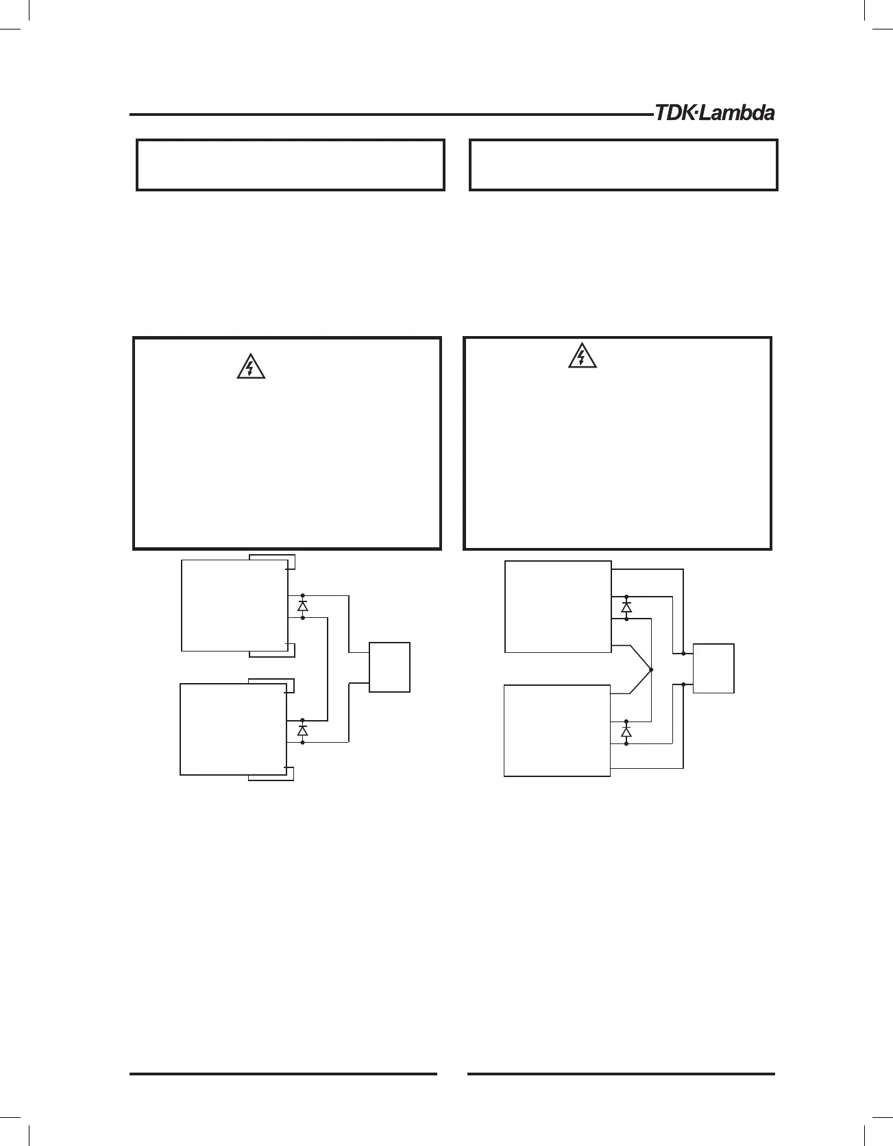
5.14.1 Series connection for increased output voltage
In this mode, two units are connected so that their outputs are summed. Set the current limit of each
power supply to the maximum that the load can handle without damage. It is recommended that
diodes be connected in parallel with each unit output to prevent reverse voltage during start up
sequence or in case one of the units shuts down. Each diode should be rated to at least the power
supply rated output voltage and output current. Refer to Fig.5-1 and 5-2 for series operation with local
+S
+
-
-S
-LS
+LS
POWER
SUPPLY
+S
+
+
-
-
-S
-LS
+LS
POWER
SUPPLY
LOAD
+S
+
-
-S
-LS
+LS
POWER
SUPPLY
+S
+
+
-
-
-S
-LS
+LS
POWER
SUPPLY
LOAD
Fig.5-1: Series connection, local sensing
Fig.5-2: Series connection, remote sensing
Remote programming in series operation for increased output voltage:
1.Programming by external voltage:
2.Using the SO function and PS_OK signal:
The analog programming circuits of this power supply
are referenced to the negative Sense (-S) potential.
Therefore, the circuits used to control each series
connected unit must be separated and floated from
each other.
The Shut-Off and PS_OK circuits are referenced to the
isolated interface common, IF_COM (J1-2,3). The
IF_COM terminals of different units can be connected
to obtain a single control circuit for the power supplies
(*)
(*)
(*)
(*)
(*) Diodes are
user supplied.
Do not connect power supplies from different
manufacturers in series or in parallel.
When power supplies are connected in series, and the
load or one of the output terminals is grounded, no point
may be at a greater potential of 60VDC from ground for
models up to 60VDC Rated Output and 600VDC from
ground for models >60VDC Rated Output. When using
RS232/485 or IEEE, refer to the OUTPUT TERMINALS
GROUNDING warning, section 3.9.11.
WARNING
CAUTION
VORSICHT
WARNUNG
Wenn Stromversorgungen in Reihe geschaltet werden
und die Last oder eine der Ausgangsklemmen geerdet
ist, stellen Sie sicher, dass
• bei Modellen mit bis zu 60V DC
Nennausgangsspannung kein Punkt ein Potential
gr er als 60V gegen ber Erde ausweistöß ü± ,
• bei Modellen mit mehr als 60V DC
Nennausgangsspannung kein Punkt ein Potential
gr er als 600V gegen ber Erde ausweist.öü
Wenn Sie RS232/485- oder EEE-SchnittstellenI
einsetzen, beachten Sie die Warnung "Erdung der
Ausgangsklemmen" in Abschnitt 3.9.11.
Schalten Sie nicht Stromversorgungen
verschiedener Hersteller in Serie oder parallel.
39