2. Setting the units as Master or Slave
a) Depress and hold the FINE button for 3 seconds. The Master/Slave configuration will be
displayed on the Current Display. Rotate the CURRENT encoder to obtain the desired mode.
Refer to Table 5-4 for the CURRENT display and modes of operation.
b) When the desired configuration is obtained, depress and release the FINE button or wait
approx. 5 seconds.
3. Master and Slave units default operation
a) When a unit is programmed to Slave mode it enters the Remote mode with Local Lockout. In
this mode, the front panel controls are disabled to prevent accidental setting change (refer to Sec.
7.2.7 for details).
b) The Slave units parameters will automatically set the following:
*Output voltage to approximate. 102% of rated output voltage.
*Programmed Current to zero.
*UVL to zero volts
*OVP to its maximum value
c) The Master and Slave modes are stored in the power supply EEPROM when the AC power is
Turned off. The system will return to the Master/Slave mode upon re-application of AC power.
4. CURRENT display accuracy
In the advanced parallel mode, the total current is programmed and reported by the Master. In
this method, the CURRENT display accuracy is 2%+/- 1 count. In cases that higher accuracy is
required, it is recommended to use the basic parallel operation mode.
5. To release units from Slave mode
Slave units can be released using the following procedure:
a) Depress FINE button for 3 seconds. The Master/Slave configuration will be displayed on the
CURRENT display.
b) Select H1 mode using the CURRENT encoder.
c) Depress FINE button again or wait 5 seconds.
d) Turn the AC power Off to store the new setting.
e) After exiting from Slave operation the unit’s parameters will be set to:
CURRENT Display
H1
H2
H3
H4
S
Operating Mode
Single supply (default)
Master supply with 1 Slave supply
Master supply with 2 Slave supplies
Master supply with 3 Slave supplies
Slave supply
Table 5-4: Setting mode of operation
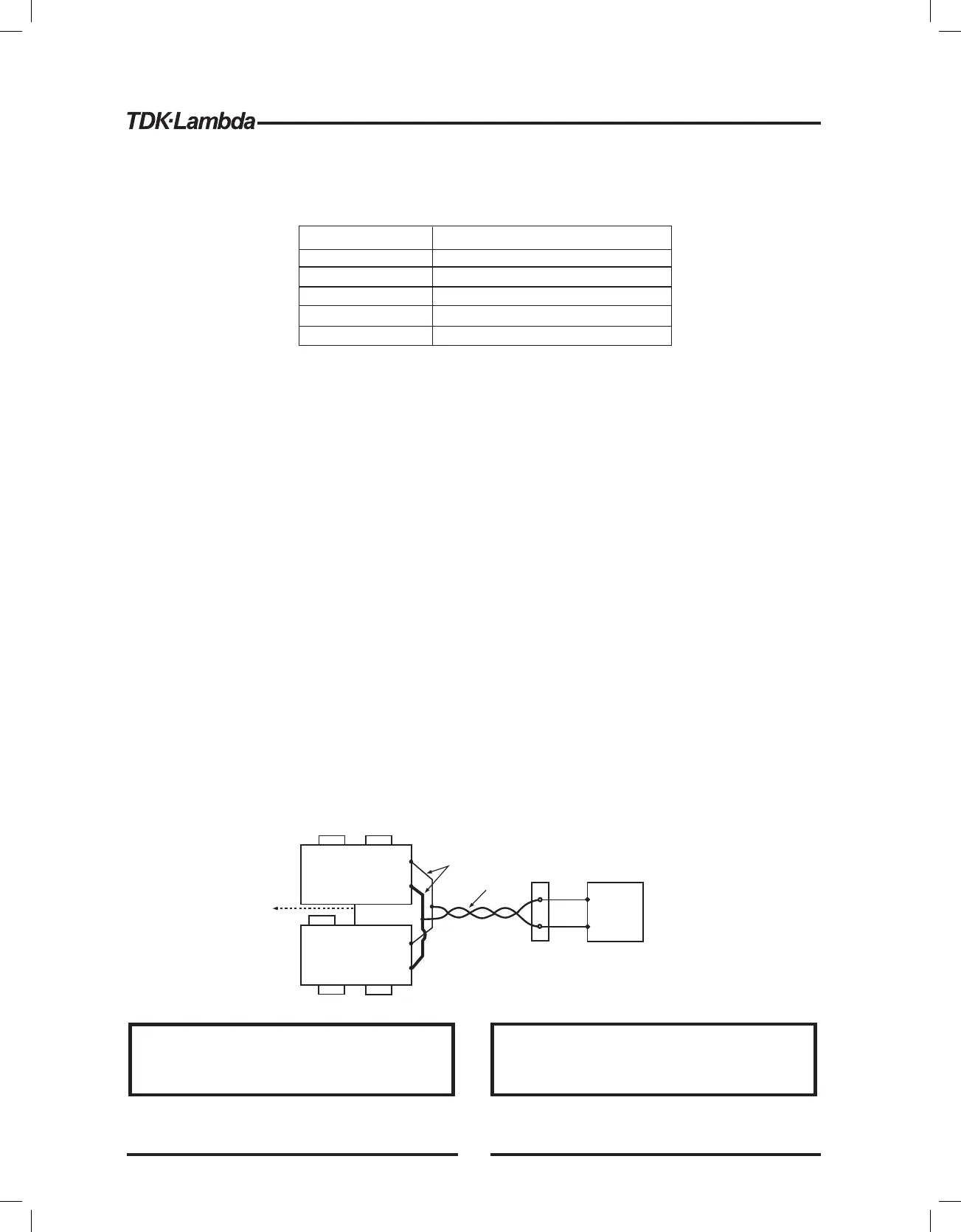
Fig.5-4: Parallel connection with local sensing
+V
-V
+V
-V
+S
+LS
-S -LS
+S
+LS
-S -LS
MASTER
POWER SUPPLY
SLAVE#1
POWER SUPPLY
+
-
LOAD
J1-25
J1-10
P
IPGM
As short as possible
Twisted
pair
To J1-10
SLAVE#2
POWER SUPPLY
J1-8
J1-12
*AST On
*OUT On
*Foldback protection Off
*Programmed Voltage to zero *AST OFF
*Programmed Current to zero *OUT OFF
*UVL to zero volts *Foldback protection OFF
*OVP to its maximum value *Locked Front Panel
Make sure that the connection between -Vo terminals is
reliable to avoid disconnection during operation.
Disconnection may cause damage to the power supply.
Stellen Sie sicher, dass die Verbindung zwischen den -V
Anschlussklemmen sich nicht w hrend des Betriebsä
l sen kann. Eine Unterbrechung kann die Netzteileö
besch digen.ä
CAUTION VORSICHT
42