Connections
Notes:
1. Make sure your hands are dry when making connections.
2. Turn power off to all components before making connections.
3. Make all connections firmly.
4. Be sure to read the operating instructions for all connected
units.
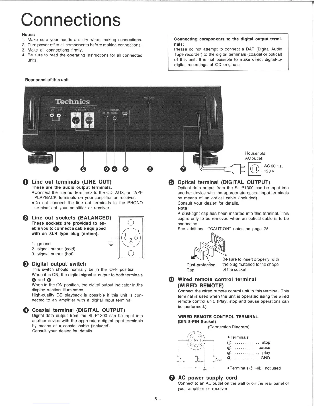
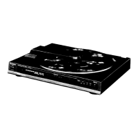
Rear panel of lhls unit
Connecilng
components to
the dfgltaf output termi-
“aIS:
Please do not attempt to connect a DAT (Digital Audio
Tape recorder) to the digital terminals (coaxial or optical)
of this unit. It is not possible to make direct digital-to-
digital recordings of CD originals.
0 Line out terminals (LINE OUT)
-.
b AAAAA
These are the audio wtp”t terminals.
*Connect the line out terminals to the CD, AUX. or TAPE
PLAYBACK terminals on your amplifier or receiver.
*Do not connect the line out terminals to the PHONO
terminals of your amplifier or receiver.
Household
0 Optical terminal (DIGITAL OUTPUT)
A
AC outlet
lol
I I
AC 60 Hz,
720”
Optical data output from the SL-P1300 can be input into
another device with the appropriate optical input terminals
by means of an optical cable (included).
Consult your dealer for details.
Note:
@ Line out sockets (BALANCED)
These sockets are provided to en-
0
able you lo connect a cable equipped
with a” XLR type plug (option),
1
36
1. ground
0
2. signal output (cold)
3. signal output (hot)
a
0
0 Digital output switch
This switch should normally be in the OFF position.
When it is ON, the digital signal is output to both terminals
Q and Q.
When in the ON position, the digital output indicator in the
display section illuminates.
High-quality CD playback is possible if this unit is con-
nected to an amplifier with a digital input terminal.
0 Coaxial terminal (DIGITAL OUTPUT)
Digital data output from the SL-P1300 can be input into
another device with the appropriate digital input terminals
by means of a coaxial cable (included).
Consult your dealer for details.
A dust-tight cap has been inserted into this terminal. This
cm is onlv to be removed when an wtical cable is to be
connected:
See additional “CAUTION” notes on page 25.
sure to insert properly, with
Dust-protection
the plug matched to the shape
Cap
of the socket.
0 Wired remote control terminal
(WIRED REMOTE)
Connect the wired remote control unit to this terminal. This
terminal is used when the unit is operated using the wired
remote control unit. (Play. stop and pause operations can
be performed.)
WIRED REMOTE CONTROL TERMINAL
(DIN B-PIN Socket)
(Connection Diagram)
*Terminals
@ ............ stop
@ .......... pause
@ ............ play
@ ............ GND
l
Terminals @--@I not used
@ AC power supply cord
Connect to an AC outlet on the wall or on the rear panel of
your amplifier or receiver.
-5-