WARNING: CAREFULLY FOLLOW THE PROCEDURE DESCRIBED BELOW.
[1]: ASSEMBLING THE ANGLE SENSOR BOARD: carefully follow the procedure
explained in paragraph “7.14.2 assembling the angle sensor board”.
[2]: REPLACING THE PIN: for the details, see “7.8.2 FITTING THE PIN”.
(*): For details see “6.1 Procedure for replacing components”, Low Kit section.
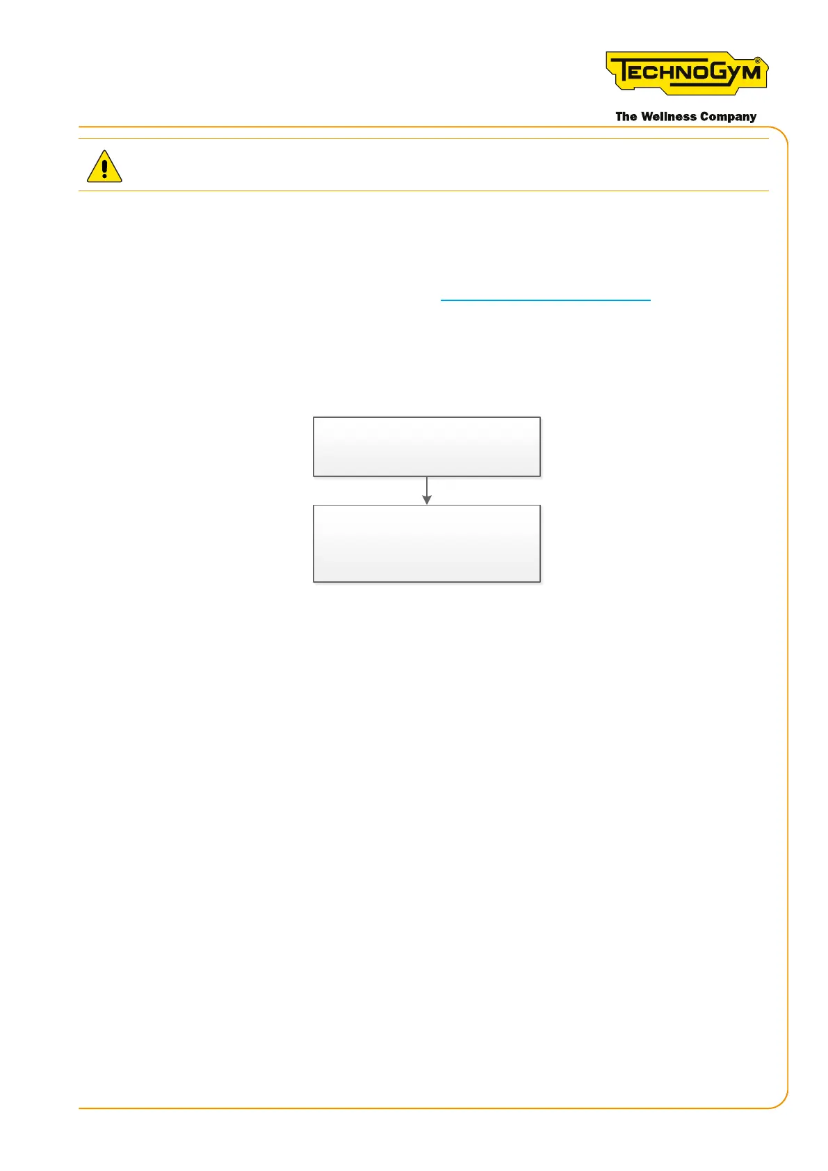
6.6.6 THE EFFORT LEVEL DOES NOT CHANGE (MECHANICAL PROBLEM)
The effort level does not change on
the display and the real resistance
perceived by the user does not change.
Mechanical problem. Check the
braking system and the cable that
connects the lever to the brake.
Figure 41
6.6.7 ABNORMAL SPEED SHOWN ON THE DISPLAY (CONSOLE VERSION)
If the Skillmill Console version shows an abnormal speed on the display (higher than the real
value), carry out the following procedure:
▪ First, always upgrade the SW to the latest released version.
▪ Replace the magnets with standard screws.
▪ Check that the distance between the RPM sensor and the closest screw is D=0.8mm (D=0.0315”)
(making a complete rotation of the pulley using a thickness gauge).
Skillmill:
Technical Service Guide - Rev. 3.5
Page 73email: support@technogym.com