TD350 Series VFD Function parameter list
-133-
Detailed parameter description
Acceleration time is the time needed for
accelerating from 0Hz to Max. output frequency
(P00.03).
Deceleration time is the time needed from
decelerating from Max. output frequency (P00.03)
to 0Hz.
TD350 series VFD defines four groups of
acceleration and deceleration time, which can be
selected via multi-function digital input terminals
(P05 group). The acceleration/deceleration time of
the VFD is the first group by default.
Setting range of P00.11 and P00.12: 0.0–3600.0s
0: Run in default direction
1: Run in reverse direction
2: Reverse running is prohibited
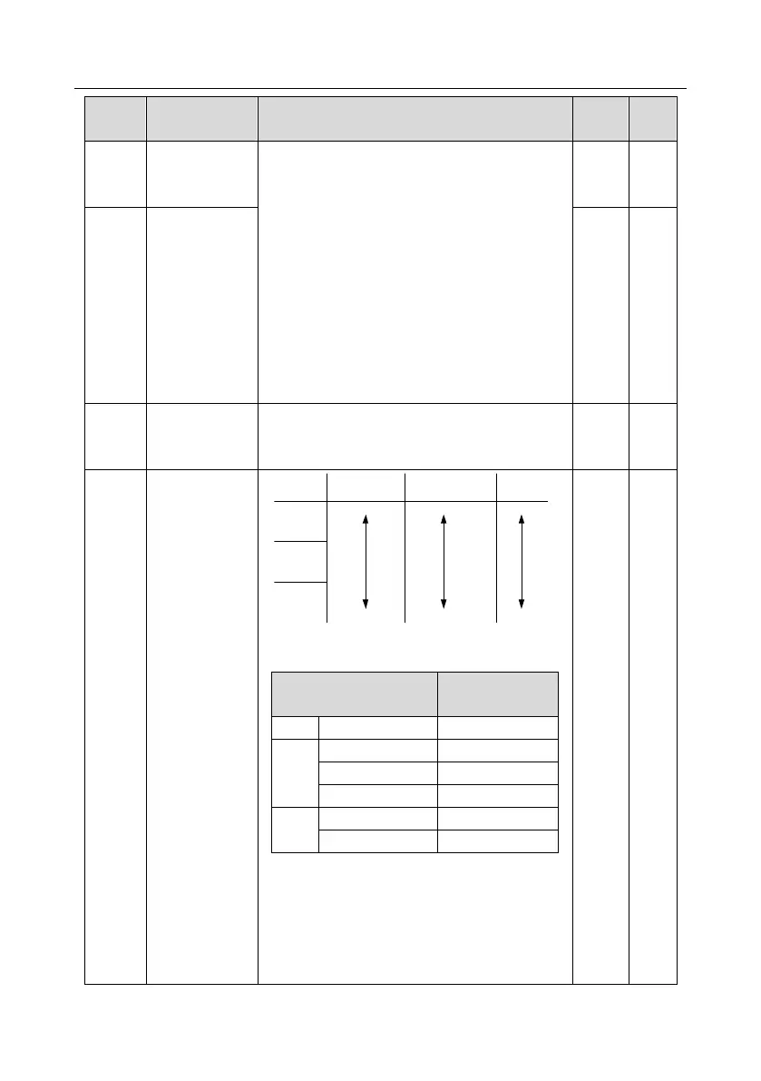
Carrier frequency
setting
Carrier
frequency
Electro magnetic
noise
Noise and leakage
current
Cooling
level
High
LowHigh
Low
High
Low
1kHz
10kHz
15kHz
The relation between the model and carrier
frequency is shown below.
Factory value of
carrier frequency
Advantages of high carrier frequency are as
follows: ideal current waveform, few current
harmonics and small motor noise.
Disadvantages of high carrier frequency are as
follows: growing switch consumption, enlarged
temperature rise, impacted output capacity; under