EasyManua.ls Logo

TECHTOP TD350 - Page 241

TECHTOP TD350
371 pages
Print Icon
To Next Page IconTo Next Page
To Previous Page IconTo Previous Page
Loading...
TD350 Series VFD Function parameter list
-236-
Function
code
Name
Detailed parameter description
Default
value
Modify
P26.28
Relay RO7
switch-off delay
0.000s
P26.29
Relay RO8
switch-on delay
0.000s
P26.30
Relay RO8
switch-off delay
0.000s
P26.31
Relay RO9
switch-on delay
0.000s
P26.32
Relay RO9
switch-off delay
0.000s
P26.33
Relay RO10
switch-on delay
0.000s
P26.34
Relay RO10
switch-off delay
0.000s
P26.35
AO2 output
selection
Same as P06.14
0
P26.36
AO3 output
selection
0
P26.37
Reserved
0
P26.38
Lower limit of
AO2 output
Above function codes define the relation between
output value and analog output. When the output
value exceeds the set max./min. output range, the
upper/low limit of output will be adopted during
calculation.
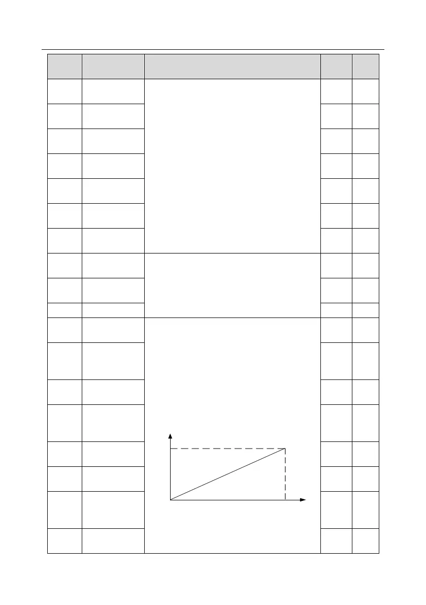
When analog output is current output, 1mA
corresponds to 0.5V voltage. In different
applications, 100% of output value corresponds to
different analog outputs.
10V (20mA)
0.0% 100.0%
AO
Setting range of P26.38: -100.0%P26.40
Setting range of P26.39: 0.00V10.00V
Setting range of P26.40: P26.38100.0%
0.0%
P26.39
Corresponding
AO2 output of
lower limit
0.00V
P26.40
Upper limit of
AO2 output
100.0%
P26.41
Corresponding
AO2 output of
upper limit
10.00V
P26.42
AO2 output filter
time
0.000s
P26.43
Lower limit of
AO3 output
0.0%
P26.44
Corresponding
AO3 output of
lower limit
0.00V
P26.45
Upper limit of
AO3 output
100.0%

Table of Contents

Other manuals for TECHTOP TD350

Related product manuals