TD350 Series VFD Installation guidelines
-24-
3-PH power supply
50/60Hz
Fuse
Input
reactor
Input
filter
DC reactor
Braking unit
Braking resistor
Output
reactor
Output
filter
VFD
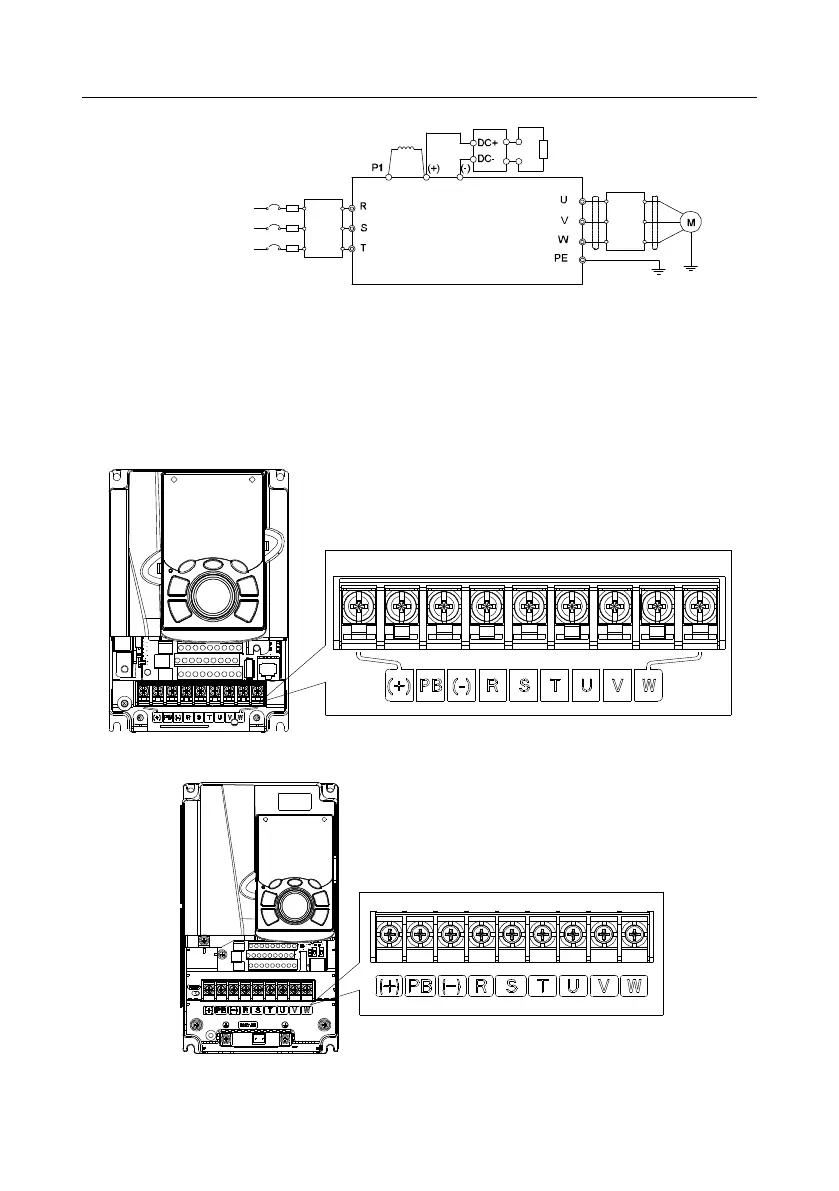
Fig 4.10 Connection diagram of main circuit for the VFDs of 575V ≥22kW
Note:
The fuse, DC reactor, brake resistor, input reactor, input filter, output reactor, and output filter
are optional parts. See Appendix D "Optional peripheral accessories" for details.
P1 and (+) are short circuited in factory. If you need to use them to connect the DC rector,
remove the contact tag between P1 and (+).
4.3.2 Main circuit terminal diagram
Fig 4.11 Terminals of main circuit for the VFDs of 220V 0.75kW and 460V 1.5–2.2kW
Fig 4.12 Terminals of main circuit for the VFDs of 220V 1.5–2.2kW, 460V 4–5.5kW, and 575V 0.75–
2.2kW