TD350 Series VFD Extension cards
-307-
Off: The extension card is disconnected from the control
board.
On: The control board feeds power to the
communication card.
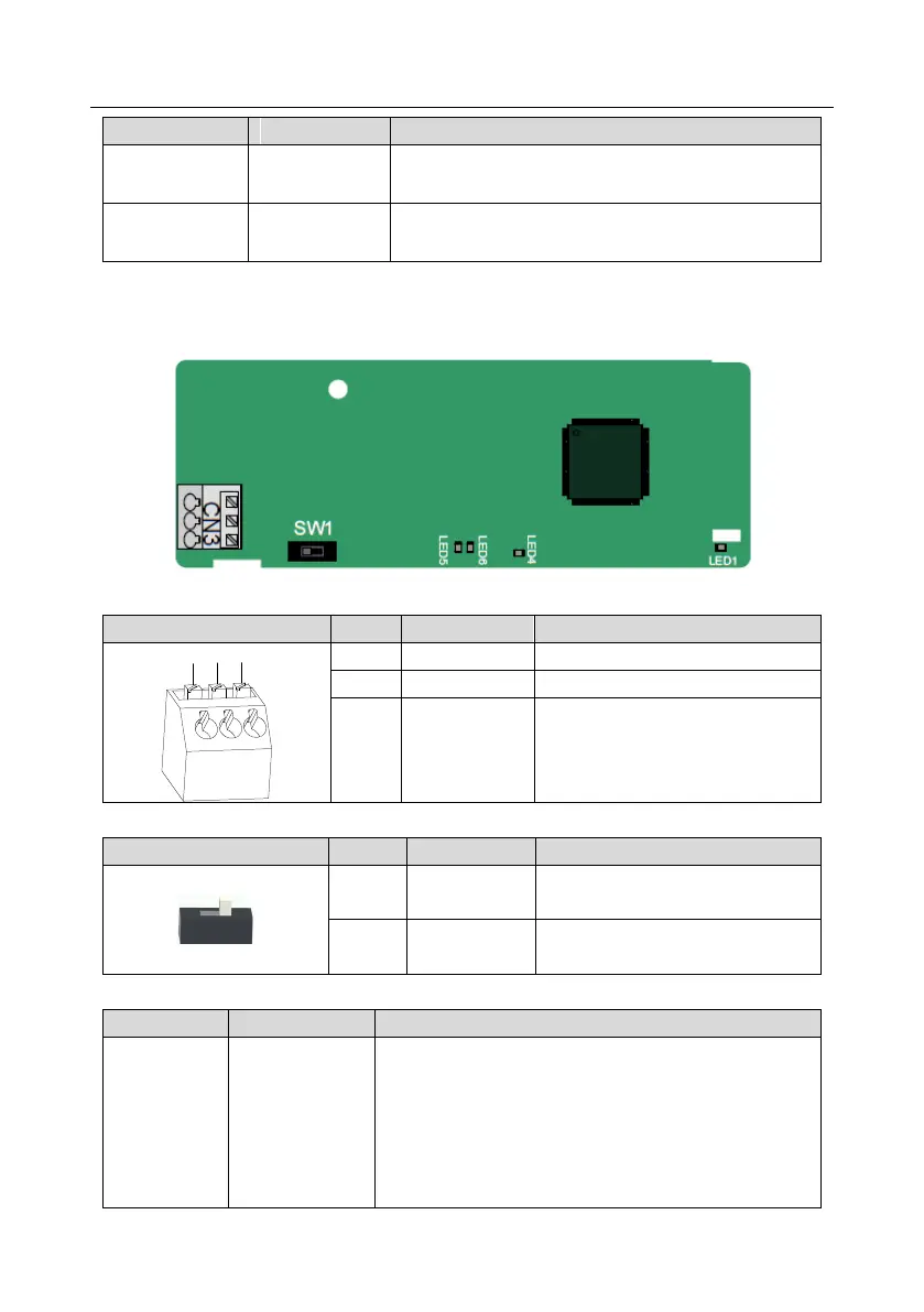
A.6.4 CANopen communication card (EC-TX505) and CAN master/slave control
communication card (EC-TX511)
The EC-TX505/511 communication card is user-friendly, adopting spring terminals.
CANopen bus high level signal
CANopen bus low level signal
Terminal resistor switch function description
CAN_H and CAN_L are not
connected to a terminal resistor.
CAN_H and CAN_L are connected to
a terminal resistor of 120 Ω.
Indicator definition
On: The extension card is establishing a connection with
the control board.
Blinks periodically: The extension card is properly
connected to the control board (the period is 1s, on for
0.5s, and off for the other 0.5s).
Off: The extension card is disconnected from the control
board.