TD350 Series VFD Extension cards
-308-
On: The control board feeds power to the communication
card.
On: The communication card is running.
Off: A fault occurs. Check whether the reset pin of the
communication card and the power supply are properly
connected.
Blinks: The communication card is in the pre-operation
state.
Blinks once: The communication card is in the stopped
state.
On: The CAN controller bus is off or a fault occurs on the
VFD.
Off: The communication card is in the working state.
Blinks: The address setting is incorrect.
Blinks once: A received frame is missed or an error occurs
during frame receiving.
For details about the operation, see the TD350 Series VFD Communication Extension Card
Operation Manual.
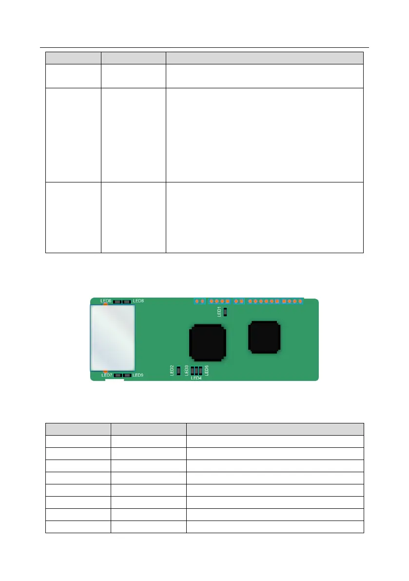
A.6.5 PROFINET communication card (EC- TX509)
The terminal CN2 adopts a standard RJ45 interface, where CN2 is the dual RJ45 interface, and these
two RJ45 interfaces are not distinguished from each other and can be interchangeably inserted. They
are arranged as follows: