TD350 Series VFD Basic operation instructions
-38-
240×160 dot-matrix LCD;
display three monitoring
parameters or six sub-menu
items simultaneously
RJ45 interface is used to
connect to the VFD.
Remove this cover when
replacing or installing clock
battery, and close the cover
after battery is installed
Mini USB terminal is used to
connect to the USB flash
drive through an adapter.
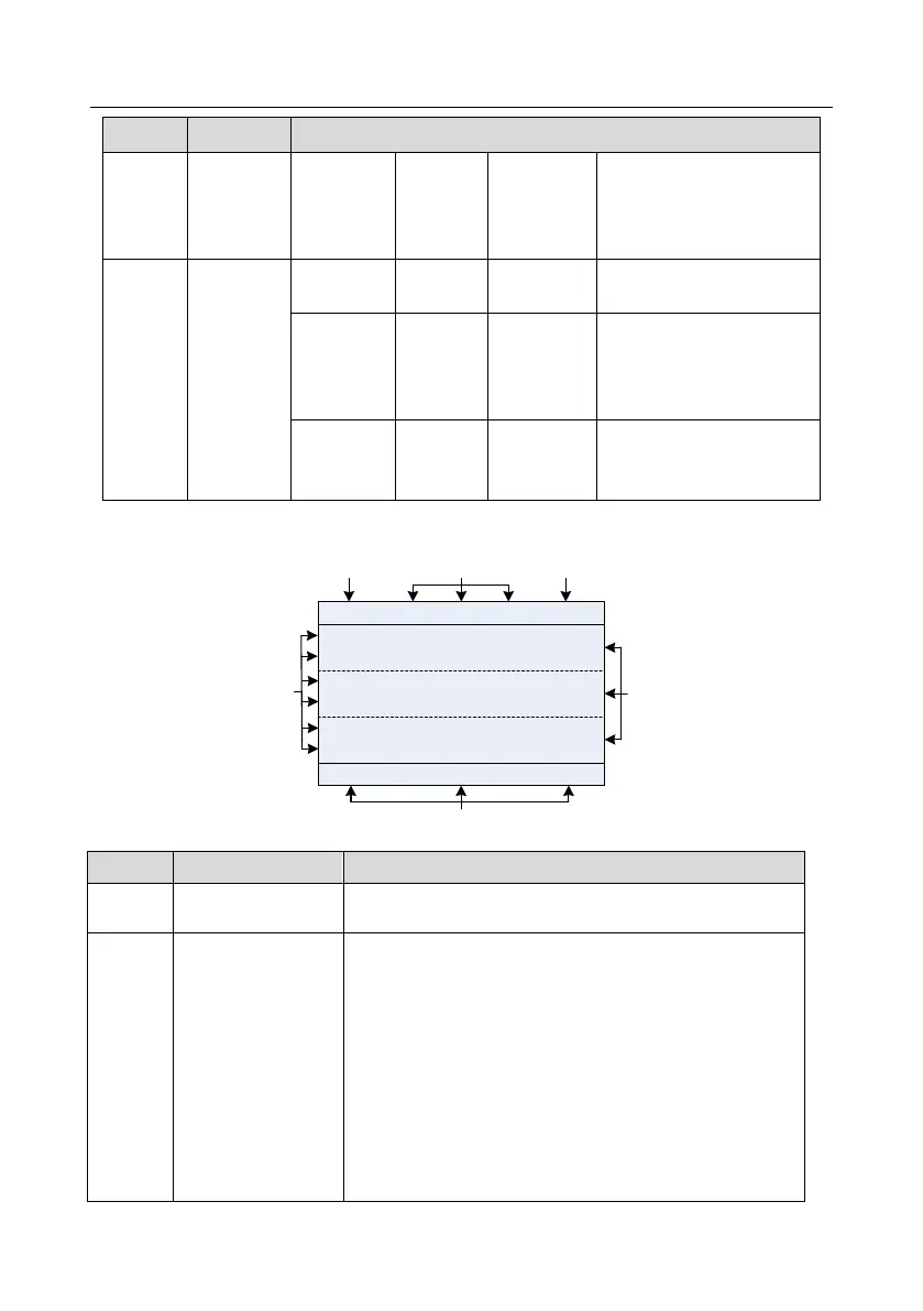
The LCD has different display areas, which displays different contents under different interfaces. The
figure below is the main interface of stop state.
01: TD350
16:02:35
Fwd
Local Ready
Motor Speed
P17.05 rpm
0
Output Cur
P17.04 A
0.0
0.00
AboutMonitor
Menu
OutputFreq
P17.01 Hz
A B C
D
E
F
Fig 5.2 Main interface of LCD
Display the real-time; clock battery is not included; the time
needs to be reset when powering on the VFD
VFD running state
display area
Display the running state of the VFD:
1. Display motor rotating direction: "Fwd" – Run forward
during operation; Rev – Run reversely during operation;
"Forbid" – Reverse running is forbidden;
2. Display VFD running command channel: "Local" –
Keypad; "Terminal" – Terminal; "Remote" - Communication
3. Display current running state of the VFD : "Ready" –
The VFD is in stop state (no fault); "Run" – The VFD is in
running state; "Jog" – The VFD is in jogging state; "Pre-alarm"
– the VFD is under pre-alarm state during running; "Fault" –
VFD fault occurred.