4-27
02- 07 ACI signal verification Scan Time
range
【1~200】2msec
02- 08 ACI Gain
range
【0 ~ 200】%
02- 09 ACI Bias
range
【0.0 ~ 100.0】%
02- 10 ACI Bias Selection
range
【0】: positive 【1】: Negative
02-11 ACI Slope
range
【0】: positive 【1】: Negative
Note:When 02-06 is set to 0 , settings of 02-07~02-11 will not be effective.
1 Parameter Description
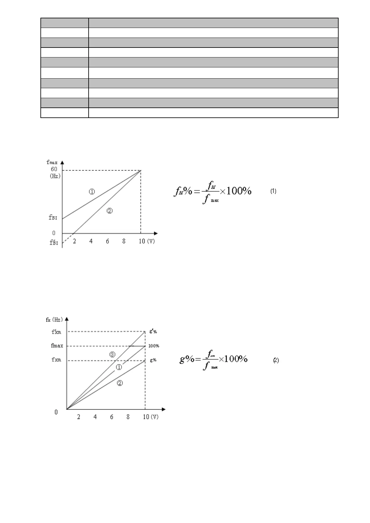
1) Bias value
When the given signal is "0", the corresponding frequency called the bias frequency with denotation fBI.
2) Frequency Gain
When the given signal is maximum value “xmax”, the percentage about ratio of the maximum “fxm” for
corresponding given frequency and the maximum output frequency “fmax” of inverter presetting, with denotation g
%.
Here, the maximum for a given frequency “fxm” of inverter not necessarily equal to the maximum frequency fmax.
1.g%<100%,the maximum frequency for actual output of inverter equal to fxm,
Like the curve ② show in Figure 2(curve ① as given line for the fundamental frequency)
2.g%>100%,the maximum frequency for actual output of inverter equal to fmax , like the curve ③ show in
Figure 2.
g%-—Percentage of Frequency Gain
fmax—The preset maximum frequency of inverter
fxm—Dummy maximum frequency
fBI%-—Percentage of Bias Frequency
fBI—Bias Frequency
fmax—Max frequency of Inverter output
 Loading...


