4-28
2. Example:
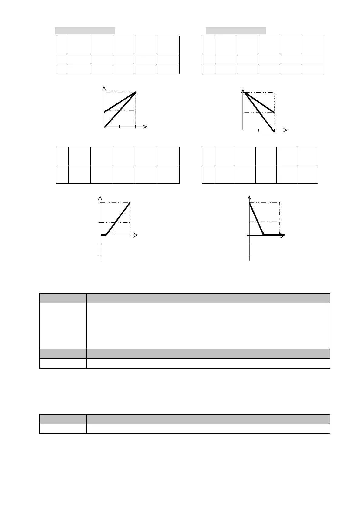
The setting of figure 4-18A: The setting of figure 4-18B:
2-02
/2-08
2-03
/2-09
2-04
/2-10
2-05
/2-11
2-09
2-02
/2-08
2-03
/2-09
2-04
/2-10
2-05
/2-11
2-09
A 100% 50% 0 0 100%
C
100%
50% 0 1 100%
B
100%
0% 0 0 100%
D
100%
0% 0 1 100%
2-02
/2-08
2-03
/2-09
2-04
/2-10
2-05
/2-11
2-09
2-02
/2-08
2-03
/2-09
2-04
/2-10
2-05
/2-11
2-09
E 100% 20% 1 0 100%
F
100%
50%
1
1 100%
1) The inverter reads the average value of A/D signals once per (02-01/02-07 x 2mS). Set scan intervals according to
possible noise interference in the environment. Increase 02-01/02-07 in an environment with noise interference, but
the response time will increase accordingly.
02-12 Analog Output Mode FM+
Range
【0】:Output frequency
【1】:Frequency Setting
【2】:Output voltage
【3】:DC Bus Voltage
【4】: Output current
02-13 Analog Output FM+ Gain
Range
【0 ~ 200】%
The multifunction analog output terminal of the terminal block (TM2), is 0~10Vdc analog output. The output type is
determined by the02-12. The output voltage level can be scaled by parameter 02-13 to suit external meters and
peripherals.
Note: the max output voltage is 10V due to hardware of the circuit. Use only devices that require a maximum of 10V
signal.
02-14 Analog Output filtering coefficient
Range
【1~100】
(00-07=60)
(00-07=60)
Hz
V
60Hz
30Hz
0Hz
E
(4mA)
(20mA)
Bias
0%
-50%
-100%
Hz
V
60Hz
30Hz
0Hz
F
(20mA)
Bias
-0%
-50%
-100%
(0mA)
(00-07=60)
Hz
V
60Hz
30Hz
Bias
0Hz
(0mA)
A
B
5V
(20mA)
100%
50%
(00-07=60)
Hz
V
60Hz
30Hz
0Hz
C
D
(20mA)
Bias
100%
50%
 Loading...


