4-40
09- 07 PID Output Lag Filter Time
Range
【0.0~2.5】Sec
09-07:Update time for output frequency.
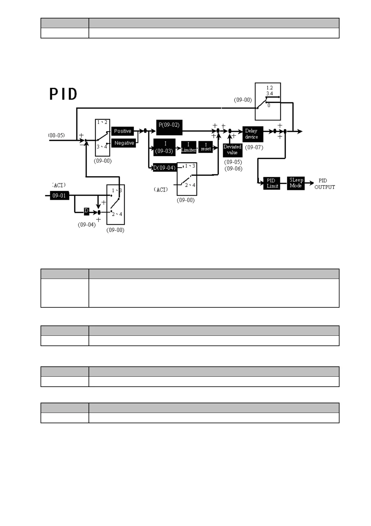
※Note:PID is used for the control of output flow of the converter, the control of external fan air
volume and temperature control, and the control flow is as
follows:
1) When performing PID control, please set the terminal ACI on TM2 as the PID feedback
signal, i.e. 02-06=0.
2) The set value described above is the frequency of the input set from 00-05/00-06.。
09- 08 PID Feedback Loss Detection Mode
Range
【0】:Disable
【1】:Enable – Drive Continues to Operate After Feedback Loss
【2】:Enable – Drive “STOPS” After Feedback Loss
09-08= 0: Disable; 09-08= 1: detect, continue running, and display ‘PDER’;09-08= 2: detect,
stop, and display ‘PDER’。
09- 09
Feedback Loss Detection Level
Range
【0~100】%
09-09: is the level for signal loss. Error = (Set point – Feedback value). When the error is larger
than the loss level setting, the feedback signal is considered lost.
09-10:the minimum time to consider the feedback signal lost.
09-11:the Limiter to prevent the PID from saturating.
09- 10
Feedback Loss Detection Delay Time
Range
【0.0~25.5】Sec
09- 11
Integration Limit Value
Range
【0~109】%
 Loading...


