< Section 9—2205 Service
DIAGRAMS AND CIRCUIT BOARD ILLUSTRATIONS
Sym bols
Graphic symbols and class designation letters are
based on ANSI Standard Y32.2-1975.
Logic symbology is based on ANSI/IEEE 91-1984.
Logic symbols depict the logic function performed and may
differ from the manufacturer's data.
The overtine on a signal name indicates that the signal
performs its intended function when It Is in the LQ state.
Abbreviations are based on ANSI Y1.1-1972.
Other ANSI standards that are used In the preparation
of diagrams by Tektronix, Inc., are:
Y14.15-1966 Drafting Practices.
Y14.2M-1979 Line Conventions and Lettering.
ANSI/IEEE 280-1985 Letter Symbols for Quantifies
Used in Electrical Science
and Electrical Engineering.
American National Standards Institute
. 1430 Broadway
New York, New York 10018
Component Values
Electrical components shown on the diagrams are in
the following units unless noted otherwise:
Capacitors Values one or greater are in picofarads (pF).
Values less than one are in microfarads OtF).
Resistors Ohms (fl).
Tlte inform ation and special symbols below may app earin this manual.
Assem bly Num bers a nd G rid C o ord in ate s
Each • assembly in the instrument is assigned an
assembly number (e.g., A20). The assembly number
appears on the circuit board outline on the diagram, in the
title for the circuit board component location illustration,
and in the lookup table for the schematic diagram and
corresponding component locator illustration. The
Replaceable Electrical Parts list is arranged by assemblies
in numerical sequence; the components are listed by
component number *(see following illustration for
constructing a component, number). -
The schematic diagram and circuit board component
location illustration have grids. A lookup table with the
grid coordinates is provided for ease of locating the
component Only the components illustrated on the facing
diagram are listed in the lookup table. When more than
one schematic diagram is used toillustratethe circuitry on
a circuit board, the circuit board illustration may only
appear opposite the first diagram on which it was il
lustrated; the lookup table will list the diagram number of
other diagrams that the circuitry of the circuit board
appears on.
Function Block Title
. E tc he d C irc u it B o a rd
Outtfned in Black
Refer to Waveform
»- —Q. »Q2
I P8 0 -W——
-
-
Rug to E C . Board
2?P82
cSwrofe
M o d ifie d C om po nen t
(Oepteted in Graft or With
GreyOudifiR) - SeePartsUst
Strap or Link
uonnaoors way
i
1 riup Indue ilpnlflea pin No i
External Screwdriver Ad|.
Assembly Number
Tektronix Part N&
for circuit board*
Selected value, see Pam List
and Maintenance Section tor
Selection Criteria
Decoupled or Filtered
Voltage
Refer to Diagram Number
Schematic Name
i
I
i
i
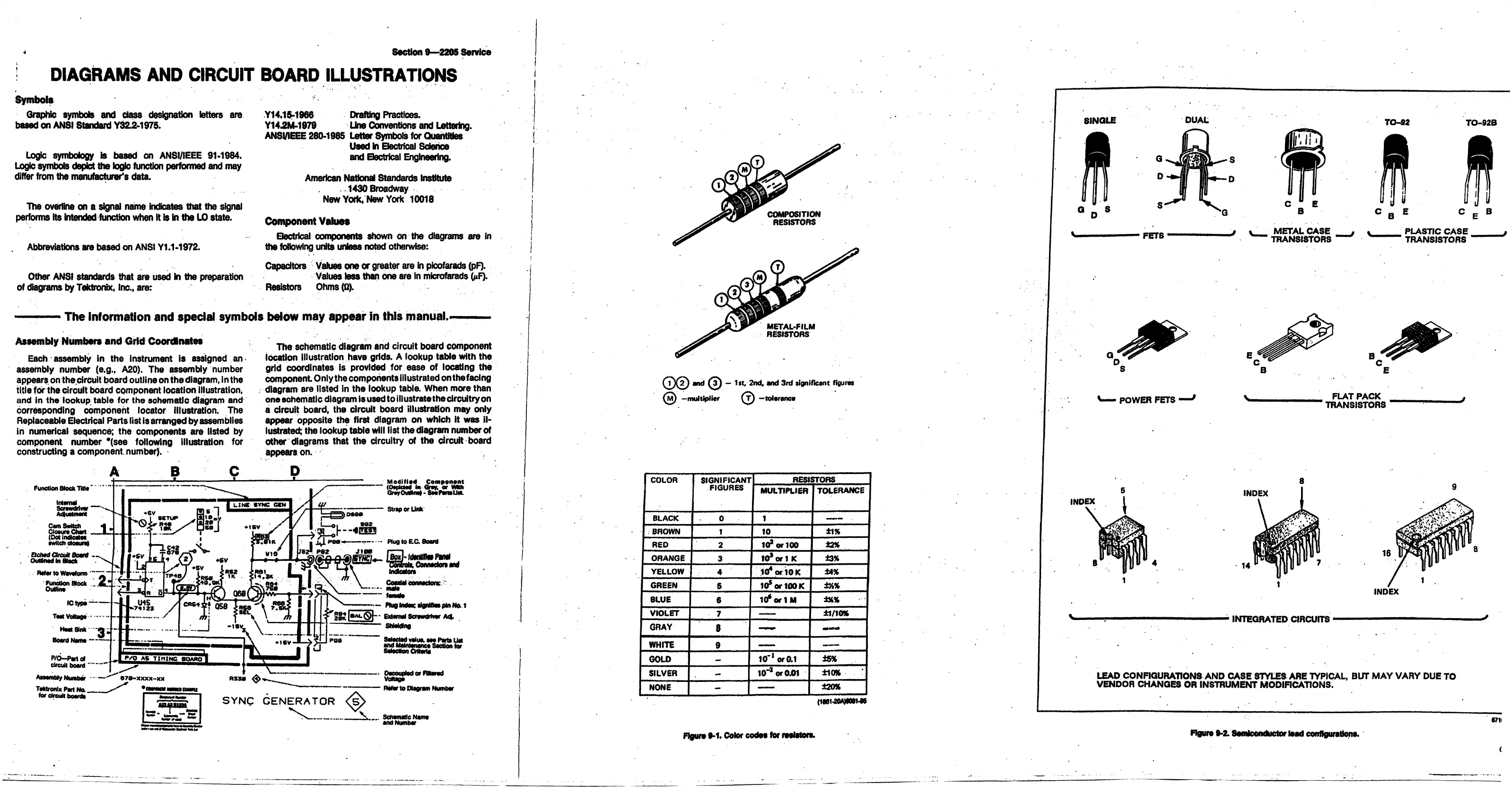
METAL-FILM
RESISTORS
0 0 © — 1st, 2nd, and 3rd significant figures
( m ) —multiplier 0 —tolerance
COLOR
SIGNIFICANT
FIGURES
RESISTORS
MULTIPLIER
TOLERANCE
BLACK
0
1
—— •
BROWN
t
10
±1%
RED
2
id * or 100 *2%
ORANGE
3
1 0 *o rt K
13%
YELLOW
4
Id * orlO K ±4%
GREEN
5
10* or tOOK
±x%
BLUE
6
ld *o r 1 M
134%
VIOLET
7
—
±1/10%
GRAY
8
—
—
WHITE
9
—
—
GOLD
—
10- ' or0.1 ±5%
SILVER
-
10"* or 0.01
±10%
NONE |
—
±20%
Figure 9-1. Color codot for resistors.
SINGLE DUAL
TO-S2 TO-92B
V
F E T S
METAL CASE , .
_______
PLASTIC CASE
TRANSI8TORS TRANSISTORS
LEAD CONFIGURATIONS AND CASE STYLES ARE TYPICAL, BUT M AY VARY DUE TO
VENDOR CHANGES OR INSTRUMENT MODIFICATIONS.
«71l
Figure 9-2. Semiconductor load configurations.
<
 Loading...


