Theory of Operation—2205 Service
Channel Switch Logic
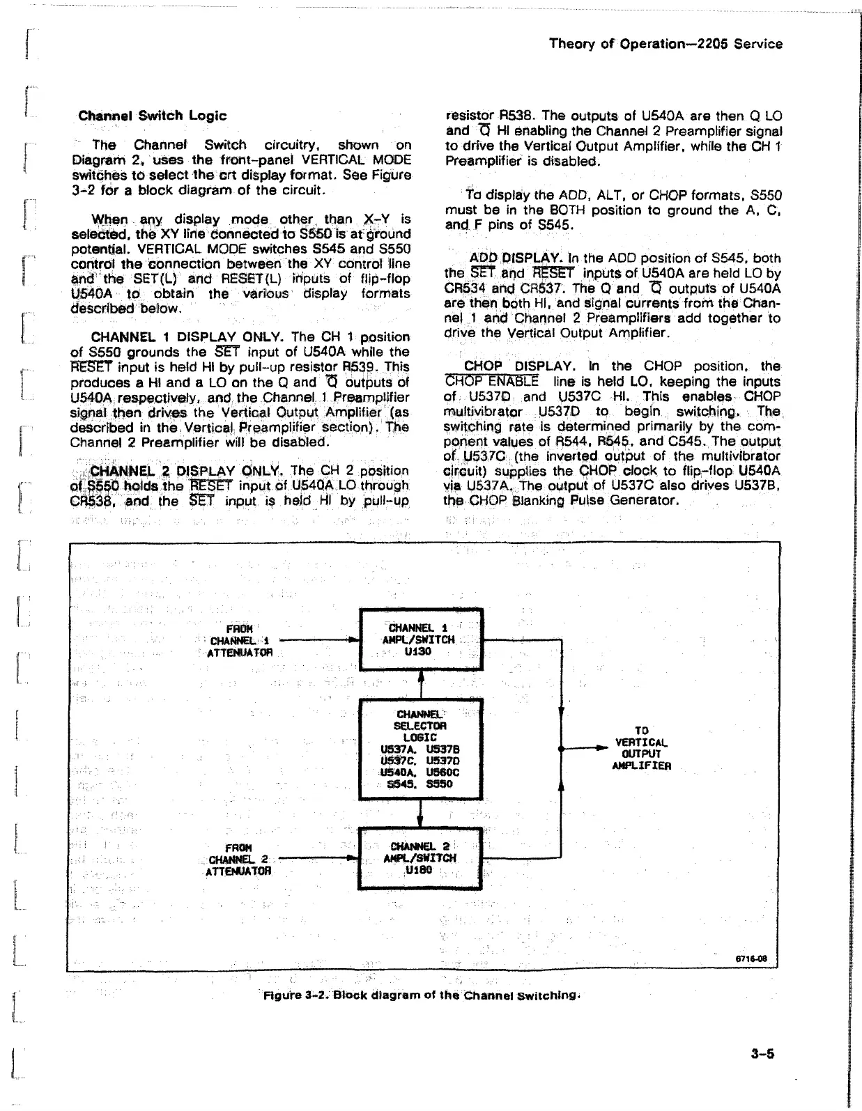
The Channel Switch circuitry, shown on
Diagram 2, uses the front-panel VERTICAL MODE
switches to select the crt display format. See Figure
3-2 for a block diagram of the circuit.
When any display mode other than X-Y is
selected, the XY line connected to S550 is at ground
potential. VERTICAL MODE switches S545 and S550
control the connection between the XY control line
and the SET(L) and RESET (L) inputs of flip-flop
U540A to obtain the various display formats
described below.
CHANNEL 1 DISPLAY ONLY. The CH 1 position
of S55Q grounds the SET input of U540A while the
RESET input is held HI by pull-up resistor R539. This
produces a HI and a LO on the Q and 75 outputs of
U540A respectively, and the Channel 1 Preamplifier
signal then drives the Vertical Output Amplifier (as
described in the Vertical Preamplifier section). The
Channel 2 Preamplifier will be disabled.
CHANNEL 2 DISPLAY ONLY. The CH 2 position
of S550 holds the RESET input of U540A LO through
CR538, and the SET input is held HI by pull-up
resistor R538. The outputs of U540A are then Q LO
and <3 HI enabling the Channel 2 Preamplifier signal
to drive the Vertical Output Amplifier, while the CH 1
Preamplifier is disabled.
fa display the ADD, ALT, or CHOP formats, S550
must be in the BOTH position to ground the A, C,
and F pins of S545.
ADD DISPLAY. In the ADD position of S545, both
the SET and RESET inputs of U54QA are held LO by
CR534 and CR537. The Q and 75 outputs of U540A
are then both HI, and signal currents from the Chan
nel 1 and Channel 2 Preamplifiers add together to
drive the Vertical Output Amplifier.
CHOP DISPLAY. In the CHOP position, the
CHOP ENABLE line is held LO, keeping the inputs
of U537D and U537C HI. This enables CHOP
multivibrator U537D to begin switching. The
switching rate is determined primarily by the com
ponent values of R544, R545, and C545. The output
of U537C (the inverted output of the multivibrator
circuit) supplies the CHOP clock to flip-flop U540A
via U537A. The output of U537C also drives U537B,
the CHOP Blanking Pulse Generator.
TO
VERTICAL
OUTPUT
AMPLIFIER
67 1648
Figure 3-2. Block diagram of the Channel Switching.
3-5